
Liquid detection cup and method for manufacturing same
A technology for detecting cups and liquids, which is applied in the direction of measuring devices, instruments, scientific instruments, etc., can solve problems such as inability to perform normal measurements, chromatographic crawling obstacles, slowing down, etc., to ensure smooth progress, good measurement results, and reduce internal problems. The effect of pressure
- Summary
- Abstract
- Description
- Claims
- Application Information
AI Technical Summary
Problems solved by technology
Method used
Image

Examples
Embodiment 1
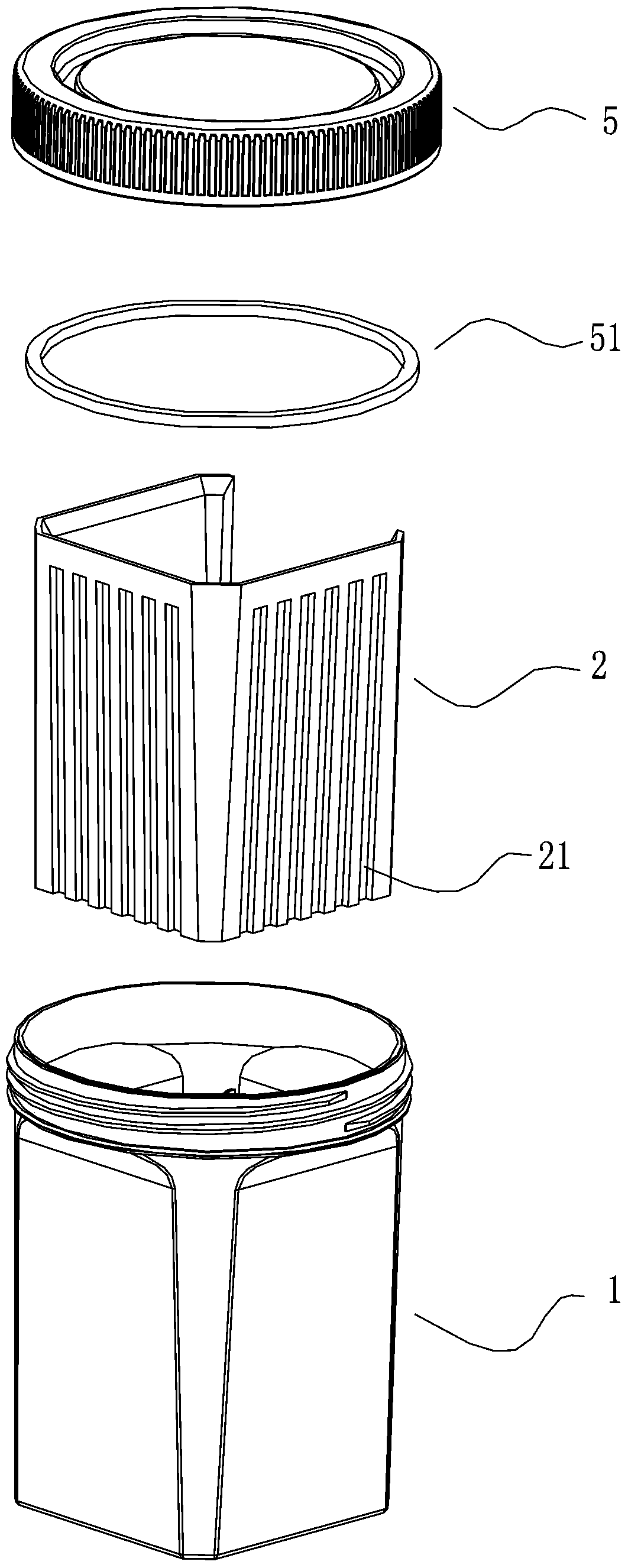
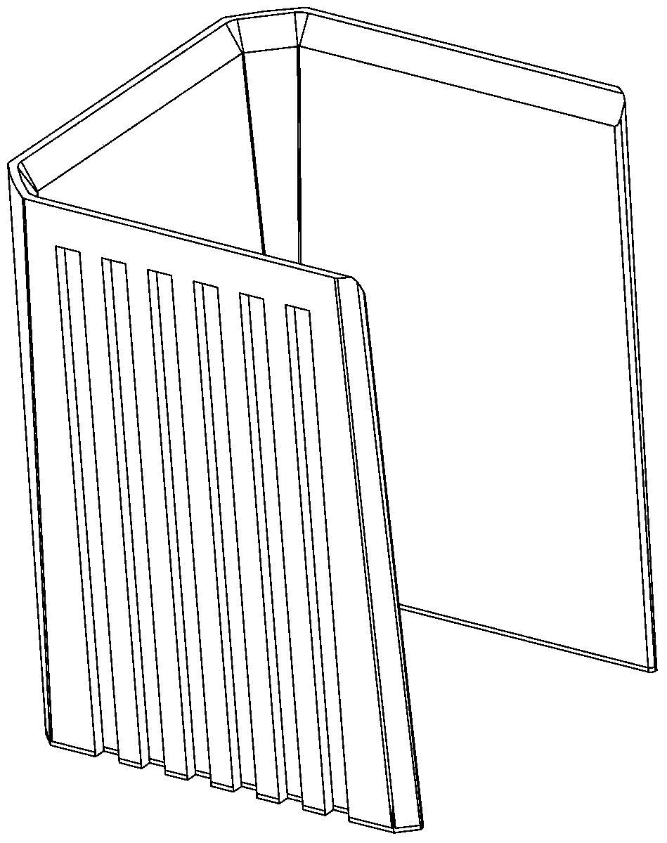
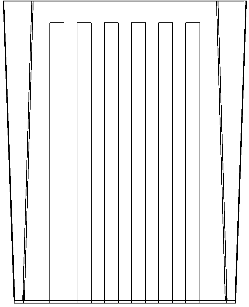
[0041] A liquid detection cup, such as figure 1 , Figure 6 As shown, it includes a cup body 1, a test paper card board 2, a test paper strip 3 and a cover film 4; placed in the test paper slot 21, such as Figure 5-6 As shown, the test strip 3 is 3 mm wide and 60 mm long; the sample application area 31 and the marking pad area 32 are 20 mm long in total, wherein the sample application area is 12 mm, and the marking pad area is 8 mm; the result display area 33 is 10 mm, and the result display area 33 is provided with detection area 331 and control area 332 again; Absorbent paper 34 parts 22mm. Described covering film 4 is transparent film, as Figure 4 As shown, the cover film 4 covers the detection surface of the test strip 2, and seals the test strip; and in Figure 4 The shaded part in the middle is coated with glue on one side, and is used for pasting with the test paper card board 2, and bonding and fixing the covering film 4. The length of the bottom edge of the cov...
Embodiment 2
[0050] Such as Figure 9 As shown, the liquid detection cup of this embodiment is basically the same as the detection cup of Embodiment 1, the main differences are:
[0051] The length of the bottom edge of the cover film from the bottom edge of the test strip is 6mm; the part of the cover film corresponding to the lower part of the test strip mark pad is provided with a through hole, and the center of the through hole is 3mm away from the lower edge of the mark pad area. The hole diameter is 1 mm.
[0052] The bottom of the cup is round.
Embodiment 3
[0054] The liquid detection cup of this embodiment is basically the same as the detection cup of Embodiment 1, the main differences are:
[0055] The length of the bottom edge of the cover film from the bottom edge of the test strip is 9mm; the cover film is provided with a through hole corresponding to the part below the test strip mark pad, and the center of the through hole is 1.5mm away from the lower edge of the mark pad area. The through-hole diameter is 1.5mm.
PUM
 Abstract
Description
Claims
Application Information