Winding-type solid electrolytic capacitor packaging structure
A technology of solid electrolysis and packaging structure, applied in the direction of electrolytic capacitors, capacitor shells/packages, capacitors, etc., can solve problems such as the design of conductive pins of wound solid electrolytic capacitors and the limitation of electrical connection methods.
- Summary
- Abstract
- Description
- Claims
- Application Information
AI Technical Summary
Problems solved by technology
Method used
Image
Examples
no. 1 example 〕
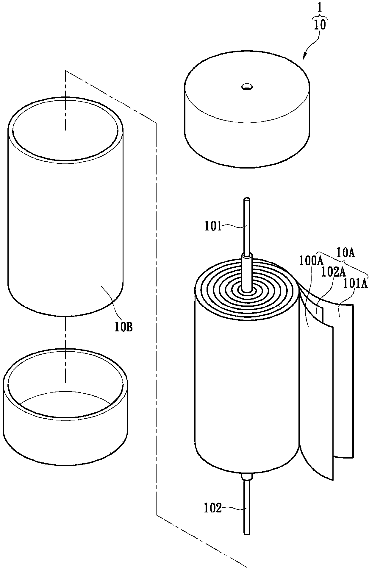
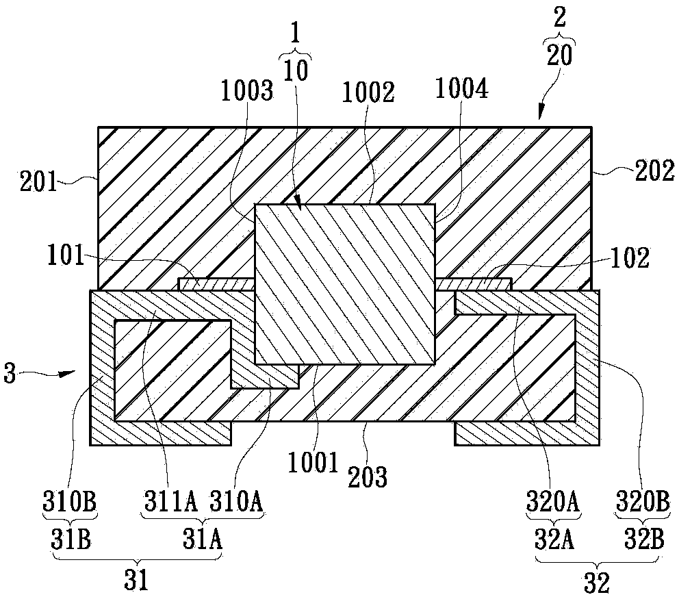
[0068] see Figure 1A to Figure 1C As shown, the first embodiment of the present invention provides a wound-type solid electrolytic capacitor packaging structure, which includes: a capacitor unit 1 , a packaging unit 2 and a conductive unit 3 .
[0069] First, if Figure 1A As shown, the capacitor unit 1 includes at least one wound capacitor 10 , wherein the wound capacitor 10 has at least one first conductive pin 101 and at least one second conductive pin 102 . Furthermore, the wound capacitor 10 includes a capacitor core 10A wound together by at least one positive foil 100A, at least one negative foil 101A and at least one separator 102A, and a wrapping capacitor core 10A. The casing 10B (the casing 10B includes an outer cover), and the insulating paper 102A is adsorbed with conductive polymers and stacked between the positive foil 100A and the negative foil 101A.
[0070] Furthermore, if Figure 1BAs shown, the package unit 2 includes a package body 20 covering the capaci...
no. 2 example
[0076] see figure 2 As shown, the second embodiment of the present invention provides a wound-type solid electrolytic capacitor packaging structure, which includes: a capacitor unit 1 , a packaging unit 2 and a conductive unit 3 . Depend on figure 2 and Figure 1B It can be seen from the comparison that the biggest difference between the second embodiment of the present invention and the first embodiment is: in the second embodiment, when the wound capacitor 10 is vertically placed in the package body 20, the wound capacitor 10 The right side end and the left side end will respectively have a first flat surface 1001 and a second flat surface 1002 due to being flattened, and the bottom end and the top end of the wound capacitor 10 have a first side surface 1003 and a first side surface 1003 respectively. a second side surface 1004 . Therefore, the L-shaped contact section 310A of the first embedded portion 31A can contact the second flat surface 1002 and the first side sur...
no. 3 example
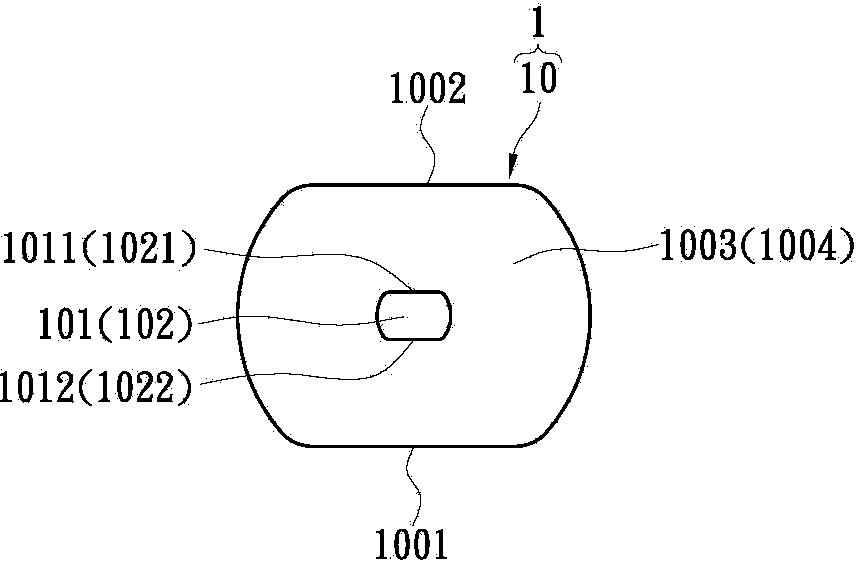
[0078] see image 3 As shown, the third embodiment of the present invention provides a wound-type solid electrolytic capacitor packaging structure, which includes: a capacitor unit 1 , a packaging unit 2 and a conductive unit 3 . Depend on image 3 and figure 2 The comparison shows that the biggest difference between the third embodiment of the present invention and the second embodiment is: in the third embodiment, both the first conductive pin 101 and the second conductive pin 102 can be connected from the first conductive pin 10 of the wound capacitor 10 The two side surfaces 1004 extend out to contact the first conductive terminal 31 and the second conductive terminal 32 respectively.
PUM
 Abstract
Description
Claims
Application Information
 - R&D
- Intellectual Property
- Life Sciences
- Materials
- Tech Scout
- Unparalleled Data Quality
- Higher Quality Content
- 60% Fewer Hallucinations
Browse by: Latest US Patents, China's latest patents, Technical Efficacy Thesaurus, Application Domain, Technology Topic, Popular Technical Reports.
© 2025 PatSnap. All rights reserved.Legal|Privacy policy|Modern Slavery Act Transparency Statement|Sitemap|About US| Contact US: help@patsnap.com


