Method for sending synchronization signals

A technology for synchronizing signals and sending methods, which is applied in digital transmission systems, electrical components, transmission systems, etc., and can solve problems such as peak-to-average ratio

Inactive Publication Date: 2013-12-04
POTEVIO INFORMATION TECH
View PDF3 Cites 43 Cited by
  • Summary
  • Abstract
  • Description
  • Claims
  • Application Information

AI Technical Summary

Problems solved by technology

[0013] As can be seen from the above formula, when the number of subbands is large, it will cause a very high peak-to-average ratio (PAPR) problem

Method used


Image

  • Method for sending synchronization signals
  • Method for sending synchronization signals
  • Method for sending synchronization signals

Examples


Embodiment 1

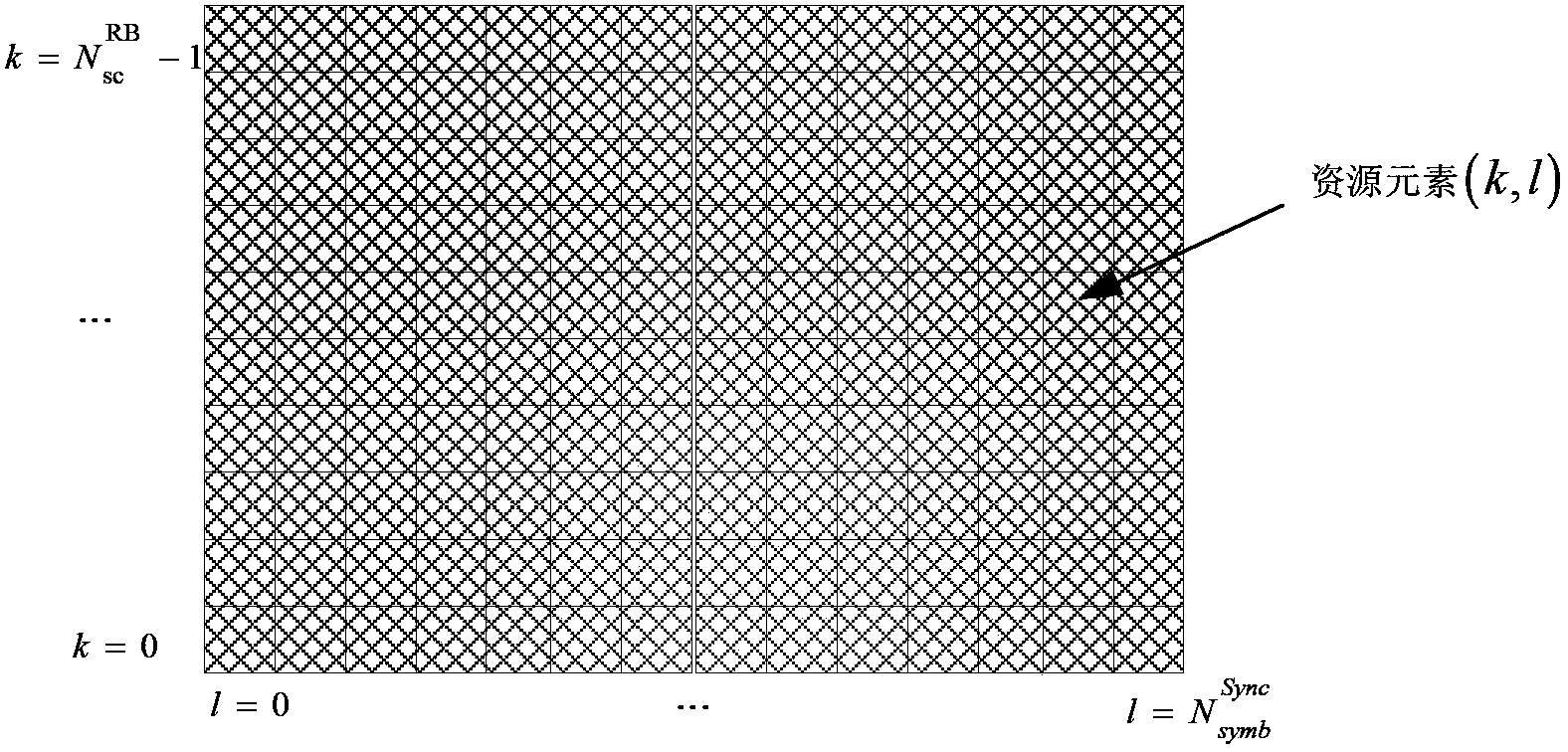
[0053] image 3 It is a schematic diagram of the configuration of the synchronization signal resource grid in the first embodiment. Such as image 3 As shown, the synchronization signal includes 10 subcarriers in the frequency domain, and includes 14 OFDM symbols in time, and the subcarrier spacing is 2kHz; wherein, l represents the lth OFDM symbol, k represents the kth subcarrier, The synchronization signal is divided into two sequences with a length of 70, and each sequence is mapped to a full subband bandwidth resource of 7 OFDM symbols. Both sequences are PN codes. The synchronization signal sending method in the first embodiment will be described in detail below.

[0054] Figure 4 It is a specific flow chart of the synchronization signal sending method in the present invention. Such as Figure 4 As shown, the method includes:

[0055] In step 401, a synchronization signal for each subband is generated according to the cell ID and the subband number.

[0056] A...

Embodiment 2

[0090] Figure 5 It is a schematic diagram of the configuration of the synchronization signal resource grid in the second embodiment. Such as Figure 5 As shown, the synchronization signal includes 42 subcarriers in the frequency domain, and includes 3 OFDM symbols in time, and the subcarrier spacing is 2kHz / 4; wherein, l represents the lth OFDM symbol, and k represents the kth subcarrier, The synchronization signal is mapped to all downlink resources in the synchronization frame. The synchronization signal sequence is a ZC sequence. The synchronization signal sending method in the second embodiment is described in detail below, the basic flow and Figure 4 same, including:

[0091] In steps 401-402, a synchronization signal of each subband is generated according to the cell ID and the subband number, and the synchronization signal is mapped to the time-frequency resource position of the synchronization signal of the corresponding subband.

[0092] ...


PUM


Abstract

The invention provides a method for sending synchronization signals. The method includes the steps that the synchronization signals of each sub-band are generated corresponding to each sub-band according to the ID of a cell and the serial number of a corresponding absolute sub-band of each sub-band, wherein the synchronization signals generated by the different sub-bands are mutually different; all points of the synchronization signals of each sub-band are mapped to the time-frequency resource positions of the synchronization signals of each sub-band where the pointes are located for transmitting, wherein time-frequency resources of the synchronization signals comprise all downlink resources on the whole sub-bands in a synchronization frame. By the application of the method for sending the synchronization signals, the peak-to-average ratio of time-domain signals can be reduced.

Description

technical field [0001] The invention relates to a synchronization technology in a communication system, in particular to a synchronization signal sending method of a private network communication system. Background technique [0002] The synchronization of the TD-LTE system adopts two kinds of specially designed physical signals, which are broadcast on each cell. They are the primary synchronization signal (PSS) and the secondary synchronization signal (SSS). The detection of these two signals not only synchronizes time and frequency, but also provides the UE physical layer cell identity and cyclic prefix length, informing the UE whether the cell is using Frequency Division Duplex (FDD) or Time Division Duplex (TDD). [0003] In a TDD cell, regardless of the system bandwidth, the time domain and frequency domain positions of the primary synchronization signal (PSS) and secondary synchronization signal (SSS) are fixed, and the PSS is located in the middle 72 sub-bands of the ...

Claims


Application Information

Patent Timeline
Patent Type & Authority Applications(China)
IPC IPC(8): H04L27/26H04L5/00
Inventor 王丽冯绍鹏王雪霞
Owner POTEVIO INFORMATION TECH
Why Eureka
Try Eureka