Separating device for separating magnetic or magnetizable particles present in a suspension

A separation equipment and magnetization technology, which is applied in the direction of magnetic separation, solid separation, high-gradient magnetic separator, etc., can solve the problem that particles cannot be separated, and achieve the effect of small current demand

Inactive Publication Date: 2013-12-04
SIEMENS AG
View PDF5 Cites 3 Cited by
  • Summary
  • Abstract
  • Description
  • Claims
  • Application Information

AI Technical Summary

Problems solved by technology

[0004] Test results in the separation device known from DE 10 2008 047 852 A1 have shown that in subregions of the separation channel an undesired force component occurs which moves the particles away from the wall of the separation channel through which flow occurs, so that a certain Particles of the share cannot be separated

Method used


Image

  • Separating device for separating magnetic or magnetizable particles present in a suspension
  • Separating device for separating magnetic or magnetizable particles present in a suspension

Examples


Embodiment Construction

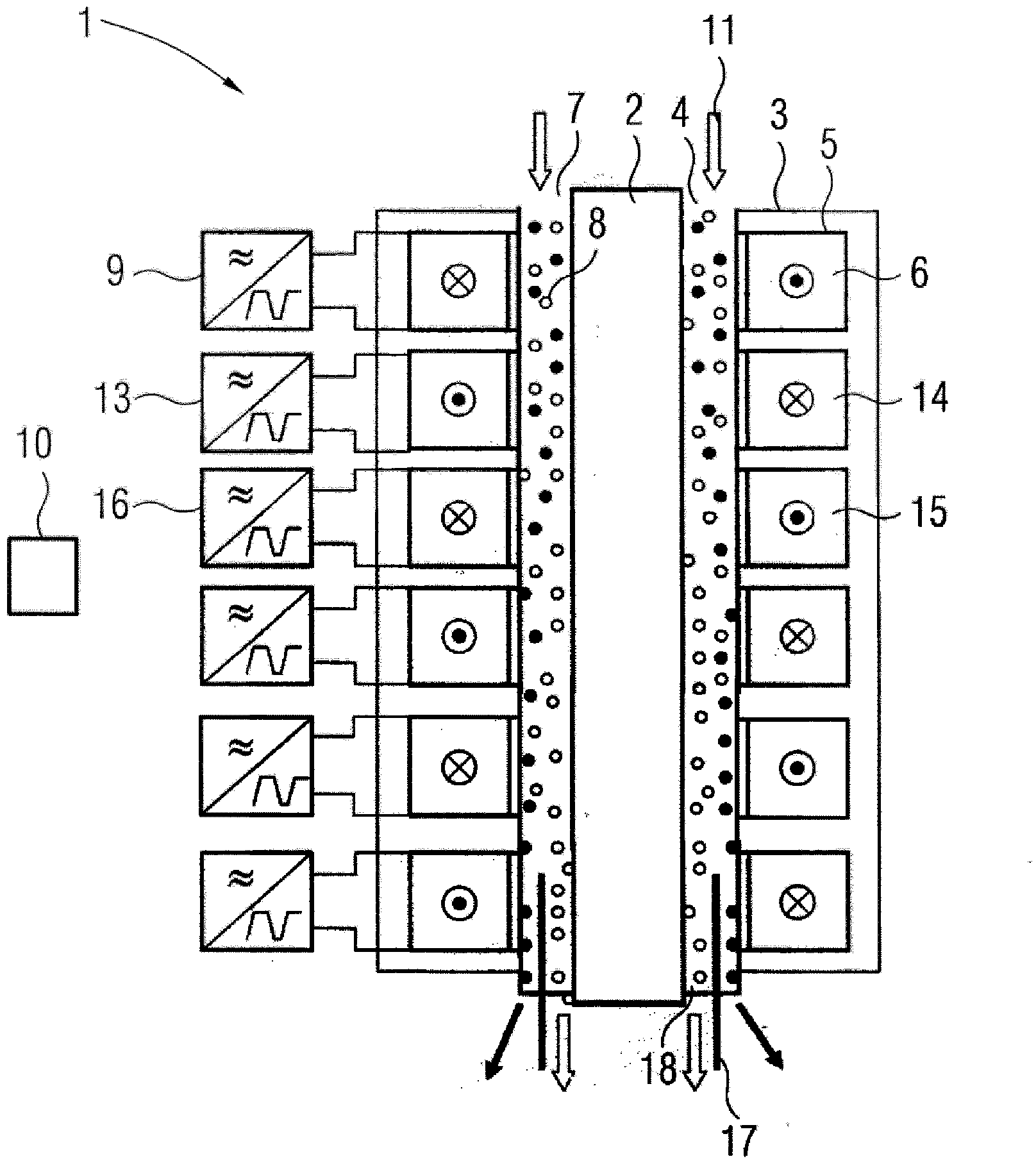
[0020] figure 1 The shown separating device 1 comprises a cylindrical extrusion body 2 which is spaced apart from and surrounded by a concentric cylindrical iron yoke 3 . An annular separation channel 4 is formed between the extrusion body 2 and the yoke 3 . The ferrous yoke has a circumferential groove 5 in which a coil 6 is arranged. The separating channel 4 and the coil 6 are separated from each other by a separating wall, not shown in detail, so that liquid flowing through the separating channel 4 does not come into contact with the coil 6 . In the exemplary embodiment shown, six coils are shown, however, this is only schematically to facilitate understanding, and the number of coils arranged one behind the other in the direction of flow can be selected arbitrarily.

[0021] The inlet 7 of the separation channel 4 is continuously supplied with suspension 8 via a supply device designed as a pump. The suspension 8 contains magnetizable and non-magnetizable constituents, s...


PUM


Abstract

A separating device has a separating channel, through which a suspension can flow, a ferromagnetic yoke arranged on one side of the separating channel and a separating element arranged at the outlet of the separating channel for separating magnetic or magnetizable particles in the suspension. A plurality of coils arranged along the separating channel are controlled by a control device to produce a magnetic deflection field. The control device produces alternating current directions for controlling neighboring coils.

Description

technical field [0001] The invention relates to a separation device for separating magnetic or magnetizable particles contained in a suspension, having a separation channel through which the suspension can flow; a ferromagnetic yoke arranged on one side of the separation channel; at least A magnetic field generating device for generating a magnetic deflection field and a separation element arranged at the outlet of the separation channel for separating magnetic or magnetizable particles, wherein the magnetic field generating device has a plurality of A coil that can be controlled by a control device. Background technique [0002] Such a separating device is known from DE 10 2008 047 852 A1. For continuous processes this separation device is suitable for separating mixtures comprising both magnetizable and non-magnetizable particles. In this separation device it is provided that a time-varying deflection magnetic field, in particular a traveling wave, is generated by means ...

Claims


Application Information

Patent Timeline
Patent Type & Authority Applications(China)
IPC IPC(8): B03C1/253B03C1/28B03C1/033
CPCB03C1/0335B03C2201/18B03C1/288B03C1/253B03C2201/22B03C1/0332
Inventor 罗伯特·戈拉杰
Owner SIEMENS AG
Why Eureka
Try Eureka