Method for machining a workpiece, tool head for a lathe, and lathe

A technology for machining tools and cutter heads, used in metal processing, metal processing equipment, tool holders, etc.

Active Publication Date: 2018-08-31
J G WEISSER SOHNE
View PDF10 Cites 0 Cited by
  • Summary
  • Abstract
  • Description
  • Claims
  • Application Information

AI Technical Summary

Problems solved by technology

However, a disadvantage of this solution can be that the structural part, which is of overall relatively high quality, has to be placed in vibrations

Method used


Image

  • Method for machining a workpiece, tool head for a lathe, and lathe
  • Method for machining a workpiece, tool head for a lathe, and lathe
  • Method for machining a workpiece, tool head for a lathe, and lathe

Examples


Embodiment Construction

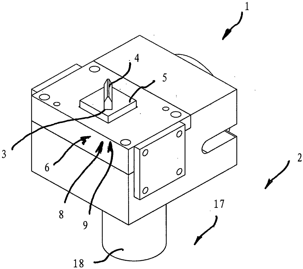
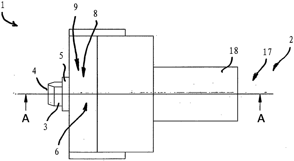
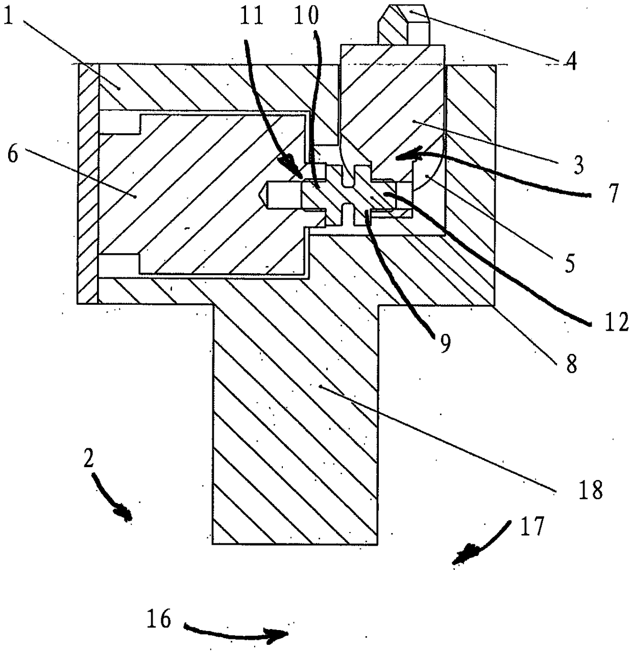
[0046] The overall figures show a cutter head generally indicated at 1 for a lathe 2 which is only largely schematically positioned at Figure 4 shown in . The cutter head 1 is provided with a machining tool 3 having a cutting portion 4 . The machining tool 3 is held by the tool holder 5 of the cutter head 1 . The cutterhead 1 has an actuator 6 which is designed to generate a movement, more precisely an additional movement, in the form of an oscillating pivoting movement of the tool holder 5 about a pivot axis 7 .

[0047] according to image 3 It can be seen that the actuator 6 is configured for generating an oscillating linear reciprocating movement and that the cutter head 1 has means 8 for converting said oscillating linear reciprocating movement into an oscillating pivoting movement of the knife holder 5 . according to image 3 and 4 , the actuator 6 for generating the oscillating linear reciprocating motion is arranged such that the oscillating linear reciprocating ...


PUM


Abstract

Tool head (1) for a lathe (2), comprising a tool holder (5) retaining a machining tool (3), the tool head (1) being equipped with at least one actuator (6) for creating an additional movement of the tool holder (5) in the form of an oscillating swiveling movement about at least one swivel pin (7). An associated method for machining a workpiece as well as an associated lathe are also disclosed.

Description

technical field [0001] The invention relates to a method for machining a workpiece by means of a cutting machining tool with a cutting portion, which is driven in rotation for generating a cutting movement and whose cutting portion is in contact with the workpiece. During the cutting engagement, and in the method, the machining tool is moved with a defined feed movement, wherein the feed movement is superimposed on an oscillating additional movement of the cutting portion of the machining tool. [0002] The invention also relates to a cutter head for a lathe with a tool holder for holding a machining tool, in particular a machining tool with at least one cutting portion, and to a lathe with a rotary drive for turning A work spindle for a workpiece, with a tool turret and with at least one cutter head mounted on the tool turret. Background technique [0003] Similar methods, cutter heads and lathes are known from the prior art in various embodiments. [0004] In known metho...

Claims


Application Information

Patent Timeline
Patent Type & Authority Applications(China)
IPC IPC(8): B23B29/12B23B5/02B23B29/20
CPCB23B5/02B23B29/125B23B29/20B23B2260/108B23B2270/10
Inventor T·雷蒂希R·约尔格
Owner J G WEISSER SOHNE
Why Eureka
Try Eureka