
Coating for a rotating plate

A feeder and turntable technology, which is applied in the direction of thin material handling, delivery of filamentous materials, transportation and packaging, etc., to achieve the effects of simplifying the manufacturing process, fast manufacturing, and saving materials

Inactive Publication Date: 2017-03-22
RIETER INGOLSTADT GMBH
View PDF5 Cites 2 Cited by
  • Summary
  • Abstract
  • Description
  • Claims
  • Application Information

AI Technical Summary

Problems solved by technology

[0003] But the disadvantage of these honeycomb protrusions is that they were originally designed and approved for processing specialized polyester types
In the polyester types of different manufacturers used today, which have mutually different properties, this effect of pulling together occurs despite the honeycomb shape of the protrusions

Method used


Image

  • Coating for a rotating plate
  • Coating for a rotating plate
  • Coating for a rotating plate

Examples


Embodiment Construction

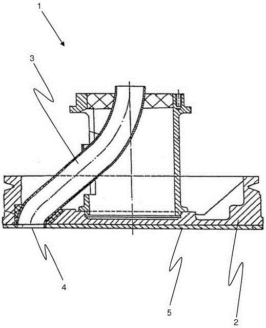
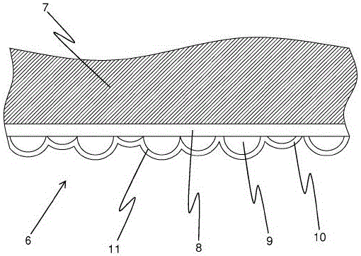
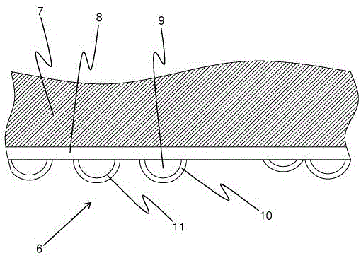
[0036] exist figure 1The schematic structure of the carousel feeder 1 is shown in . The carousel feeder 1 here consists of a base body 2 and a fiber web channel 3 arranged in the base body 2 . A fiber ribbon (not shown here) is drawn through this fiber ribbon channel 3 and leaves the carousel feeder 1 downwards through the fiber ribbon channel 3 and the opening 4 of the base body 2 . The cover 5 is attached to the base body 2 on the underside of the carousel 1 and likewise has an opening 4 . In the intended use of the carousel feeder 1 , the lower side is the side facing the cans. A coating 6 is applied to the lower surface or underside of the cover 5 , which coating is illustrated in detail in FIG. 2 .

[0037] Figure 2a A cross-section of a coating 6 is shown with spherical, irregular protrusions 11 . The coating 6 is applied to the primer 7 . The primer 7 can be part of the cover 5 or part of the base body 2 . This coating 6 has three individual layers, namely a bas...


PUM

PropertyMeasurementUnit
sizeaaaaaaaaaa

Abstract

The invention relates to a rotating plate of a spinning machine, in particular a drawframe or carding machine, for depositing a fiber band in a can, comprising a base body (2) and a sliver channel (3) arranged in the base body (2). According to the invention, it is proposed that, for the intended use of the rotating plate (1), the side of the rotating plate (1) facing the can has at least partially a coating (6) with a spatial structure of spherical, irregular elevations (11).

Description

technical field [0001] The invention relates to a carousel feeder and a method for manufacturing a carousel feeder of a weaving machine, in particular a draw frame or a tufting machine, for placing fiber strips in jars, It has a base body and fiber ribbon channels arranged in the base body. Background technique [0002] From DE 103 34 758 B4 is known a carousel feeder for a weaving machine, in particular a draw frame, a cashmere machine or a combing machine. When the machine is running, the carousel feeder and the fiber strip to be processed in the machine come into contact here. The underside of the carousel feeder, which is in contact with the fiber strip, has a three-dimensional structure at least in sections, formed of elevations and depressions, wherein the elevations are formed in a honeycomb-like manner. The effect of this three-dimensional structure is generally, the friction between the carousel feeder and the fiber strip is not reduced when they are in contact. ...

Claims


Application Information

Patent Timeline
Patent Type & Authority Applications(China)
IPC IPC(8): B65H54/80C25D5/16
CPCB65H54/80C25D5/16B65H2701/311C25D7/00C25D5/605B65H67/0428B65H2701/31D01G27/00
Inventor 迈克尔·斯特罗贝尔伊马德廷·卡拉拉尔G·施魏格尔
Owner RIETER INGOLSTADT GMBH
Learn More