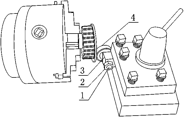
Belt wheel check ring riveting mechanism
A technology of riveting mechanism and pulley, which is applied in the field of riveting mechanism of pulley retaining ring, can solve the problems of poor reliability of stamping riveting processing and affect the appearance of products, etc., and achieve the effect of simple structure, guaranteed spinning effect, and convenient manufacturing
- Summary
- Abstract
- Description
- Claims
- Application Information
AI Technical Summary
Problems solved by technology
Method used
Image
Examples
Embodiment 1
[0024] Such as figure 1 As shown, the riveting mechanism of the pulley retaining ring includes a pressure roller shaft 1, a mounting seat 3 and a pressure roller 4, the upper surface and the lower surface of the mounting seat 3 are planes parallel to each other, and the pressure roller shaft 1 is fixed to the side of the mounting seat 3 The pressure roller 4 is disc-shaped, and the pressure roller 4 is fixedly connected to the pressure roller shaft 1 .
[0025] The set mounting seat 3 is used to be installed on the tool holder of the existing bedroom lathe, the retaining ring is pre-pressed in the riveting ring on the side of the pulley, and then the pulley is clamped on the chuck of the lathe, and then the tool holder is adjusted position, so that the plane of the retaining ring is tangent to the side of the pressure roller 4, and then start the lathe, the pulley rotates with the chuck, and then brake the turning tool holder, so that the turning tool holder moves toward the c...
Embodiment 2
[0027] This embodiment is further improved on the basis of embodiment 1, as figure 1 As shown, the mounting seat 3 is in the shape of a cuboid, and the side surfaces of the pressure roller 4 and the connecting surface between the pressure wheel shaft 1 and the mounting seat 3 are parallel to each other.
[0028] The purpose of this setting is that when the connecting surface of the pressure roller shaft 1 and the mounting seat 3 is parallel to the adjacent side of the turning tool holder, the turning tool holder is turned so that the side of the turning tool holder is parallel to the center line of the chuck, and the pressure roller 4 is relatively The pulley is vertical, which is beneficial to adjust the position of the present invention relative to the pulley.
[0029] It also includes a connecting nut 2. The pressure roller shaft 1 is a stepped shaft with an external thread at one end. The center of the pressure roller 4 is provided with a through hole. The mounting seat 3 ...
PUM
 Abstract
Description
Claims
Application Information
 - R&D
- Intellectual Property
- Life Sciences
- Materials
- Tech Scout
- Unparalleled Data Quality
- Higher Quality Content
- 60% Fewer Hallucinations
Browse by: Latest US Patents, China's latest patents, Technical Efficacy Thesaurus, Application Domain, Technology Topic, Popular Technical Reports.
© 2025 PatSnap. All rights reserved.Legal|Privacy policy|Modern Slavery Act Transparency Statement|Sitemap|About US| Contact US: help@patsnap.com

