Gear milling machine for forming inner gear ring
A technology for forming, milling, and ring gear, applied in gear teeth, mechanical equipment, large fixed members, etc., can solve the problems of small change in the size of the maximum and minimum ring gear, overhang of the milling head, and easy wear of the turbine worm. It is not easy to accurately locate, easy to wear, and the effect of rigid reinforcement
- Summary
- Abstract
- Description
- Claims
- Application Information
AI Technical Summary
Problems solved by technology
Method used
Image

Examples
Embodiment Construction
[0021] As shown in the figure, the specific implementation method is as follows:
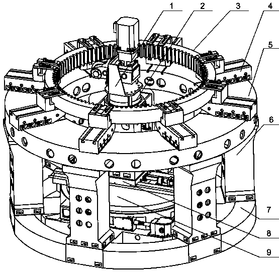
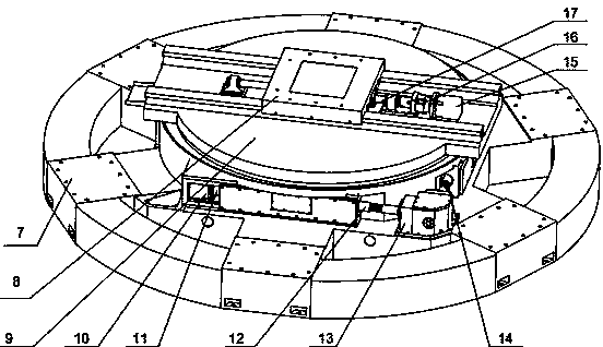
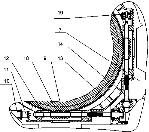
[0022] A milling machine for forming an inner ring gear, comprising a rotary guide rail component, a column component, a milling head component, a milling head bracket 1, a disc-shaped workpiece platform 5 with a central hole, a platform pillar 6 and a workpiece support 4, the The rotary guide rail components are composed of a rotary platform 9 with a guide rail on the upper surface, a horizontal slide seat 8, an integral base 7, and a driving device that provides power for the rotary platform 9 and the horizontal slide seat 8. The rotary platform 9 is installed on the integral base. 7, the center of rotation of the rotary platform 9 coincides with the center of the integral base 7, the horizontal sliding seat 8 is matched with the guide rail on the upper surface of the rotary platform 9, the column parts are fixed on the horizontal sliding seat 8, and the milling head parts pass through the mill...
PUM
 Abstract
Description
Claims
Application Information
 - Generate Ideas
- Intellectual Property
- Life Sciences
- Materials
- Tech Scout
- Unparalleled Data Quality
- Higher Quality Content
- 60% Fewer Hallucinations
Browse by: Latest US Patents, China's latest patents, Technical Efficacy Thesaurus, Application Domain, Technology Topic, Popular Technical Reports.
© 2025 PatSnap. All rights reserved.Legal|Privacy policy|Modern Slavery Act Transparency Statement|Sitemap|About US| Contact US: help@patsnap.com