Composite fixture with controllable pressure

A fixture and pressure technology, applied in the direction of clamping, manufacturing tools, support, etc., can solve the problems of low versatility of special fixtures and difficult control of clamping pressure, and achieve the effects of simple structure, increased versatility and reasonable design

Inactive Publication Date: 2013-12-11
WUXI YICHEN MOLD TECH
View PDF8 Cites 23 Cited by
  • Summary
  • Abstract
  • Description
  • Claims
  • Application Information

AI Technical Summary

Problems solved by technology

[0003] Aiming at the problems that the clamping pressure caused by the existing machine tool fixtures is not easy to

Method used


Image

  • Composite fixture with controllable pressure
  • Composite fixture with controllable pressure
  • Composite fixture with controllable pressure

Examples


Embodiment 1

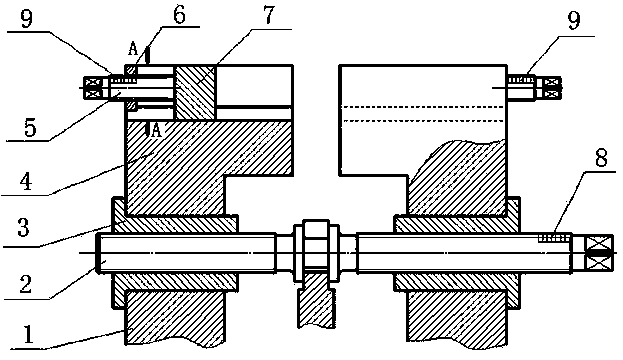
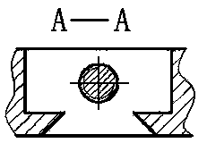
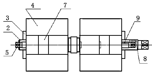
[0019] like figure 1 , figure 2 , image 3 As shown, the pressure controllable compound fixture includes fixture seat, slide rail 1, large adjusting screw 2, moving block 3, large clamping block 4, small adjusting screw 5, fixed block 6, small clamping block 7, scale A8, Scale B9, the lower end of the slide rail 1 is installed on the fixture seat, the upper end of the slide rail 1 is stuck on the concave edge of the lower end of the moving block 3, the large adjusting screw 2 is engaged with the moving block 3, and the large adjusting screw 2 is engaged with the moving block 3. The lower end of the clamping block 4 is pressed on the concave edge of the upper end of the moving block 3, and the upper end of the large clamping block 4 is provided with a groove. The vertical section of the upper part of the groove is rectangular, and the lower part of the groove is a dovetail groove. The fixed block 6 is fixed on the side end of the groove of the large clamping block 4, the upp...


PUM


Abstract

The invention discloses a composite fixture with controllable pressure, and belongs to the field of machine tool fixtures. The composite fixture with the controllable pressure comprises a fixture base, a sliding rail, a large adjusting screw rod, a moving block, a large clamping block, a small adjusting screw rod, a fixing block, a small clamping block, a scale A and a scale B, the lower end of the sliding rail is mounted on the fixture base, the upper end of the sliding rail is clamped in the concave edge of the lower end of the moving block, the large adjusting screw rod is meshed with the moving block, the lower end of the small clamping block is embedded in a dovetail groove of the lower end of a groove formed in the large clamping block, the small adjusting screw rod is meshed with the fixing block, one end of the small adjusting screw rod is fixedly connected with the small clamping block, the scale A is arranged on the large adjusting screw rod, and the scale B is arranged on the small adjusting screw rod. The composite fixture with the controllable pressure solves the problems that the clamping pressure of an existing machine tool fixture is difficult to control and a special fixture is not high in universality, and has the advantages of being simple in structure, reasonable in design and easy to manufacture.

Description

technical field [0001] The invention belongs to the field of machine tool clamps, and more specifically relates to a pressure-controllable composite clamp. Background technique [0002] In the machinery manufacturing industry, lathes are widely used to process various parts. When processing parts, the problem of clamping and positioning is involved. At present, when the existing fixture is working, in the process of frequent clamping and loosening, the tightness of the clamping of the workpiece is usually judged by hand acting on the workpiece, which consumes a lot of time, increases labor intensity, and reduces work efficiency. Therefore, it is necessary to design a fixture that can easily control the clamping pressure when the workpiece is clamped. For enterprises, in order to reduce costs, the versatility of fixtures should also be considered, and at the same time, it is necessary to ensure that the clamping pressure of the workpiece is easy to control when clamping. C...

Claims


Application Information

Patent Timeline
IPC IPC(8): B23Q3/06
Inventor 钱根来李康魏鑫夏守忠陈微霞丁亭
Owner WUXI YICHEN MOLD TECH
Why Eureka
Try Eureka