Deformation compensation device for injection molding machine or die-casting machine
A deformation compensation and die-casting machine technology, applied in the field of deformation compensation devices, can solve problems such as poor stability and inconvenient installation and assembly of elastic compensation components, and achieve the effects of ensuring accuracy, improving independence and scope of application, and ensuring sealing performance
- Summary
- Abstract
- Description
- Claims
- Application Information
AI Technical Summary
Problems solved by technology
Method used
Image

Examples
Embodiment 1
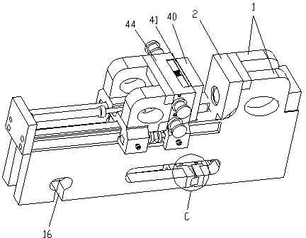
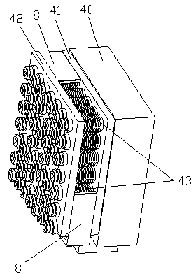
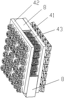
[0031] see Figure 1-4 , the deformation compensating device for injection molding machine or die-casting machine of the present invention includes a first base plate 41, a second base plate 42, and an elastic connector 43 arranged between the first base plate 41 and the second base plate 42 The first base plate 41 is connected to the side of the movable template 40 opposite to the mold core, and the second base plate 42 is fixedly connected to the movable mold support 44; the elastic connector 43 includes a 41 and the elastic member 433 between the second base plate 42, and a pre-tightening device, the pre-tightening device is used to connect the elastic member 433 to the first base plate 41 and the first base plate 41 with a certain pre-tightening force. Between the second substrate 42 .
[0032] In this example, if Figure 7 As shown, a cavity for placing the deformation compensation device is formed on the movable mold support 44, and the deformation compensation device ...
Embodiment 2
[0040] see Figure 7-9 , On the basis of Embodiment 1 above, the deformation compensation device further includes a rapid pressurization and decompression device for pressurizing or depressurizing the elastic member 433 . The rapid pressurization and pressure relief device includes a driving device 7 that drives the screw 431 to rotate, and a movable block 437 and a top block 438 that are located between the movable template 40 and the end of the screw 431 and are connected in contact with each other. , the movable block 437 is plugged into the bolt head of the screw rod 431 in a circumferential limit, and the top block 438 is arranged in a groove on the movable template 40 in a circumferential limit. In this embodiment, the top block 438 is rectangular, the movable block 437 is circular, and the surface of the movable template 40 that matches the first base plate 41 is provided with a blind hole, the shape of the blind hole is consistent with the shape of the horizontal proj...
Embodiment 3
[0044] On the basis of the above-mentioned embodiment 1 and embodiment 2, the deformation compensation device for the die-casting machine or the injection molding machine of the present invention also includes being installed under the frame 1 of the die-casting machine or the injection molding machine, for Second deformation compensation device for deformation compensation, see figure 1 Part C in and Figure 5-6 .
[0045] The second deformation compensating device is installed in the gap at the bottom of the frame 1, and includes a pair of guide blocks 51, and the two guide blocks 51 are arranged at intervals along the compression direction of the gap; The opening device is arranged between the two guide blocks, and the expansion device drives the guide block 51 to squeeze to both sides of the notch, that is, to move to both sides of the notch below the frame 1 .
[0046] In this embodiment, the gap between the two guide blocks 51 forms a wedge-shaped cavity; the expansion...
PUM
 Abstract
Description
Claims
Application Information
 - Generate Ideas
- Intellectual Property
- Life Sciences
- Materials
- Tech Scout
- Unparalleled Data Quality
- Higher Quality Content
- 60% Fewer Hallucinations
Browse by: Latest US Patents, China's latest patents, Technical Efficacy Thesaurus, Application Domain, Technology Topic, Popular Technical Reports.
© 2025 PatSnap. All rights reserved.Legal|Privacy policy|Modern Slavery Act Transparency Statement|Sitemap|About US| Contact US: help@patsnap.com