Electric power bicycle driving system capable of recognizing state of road

A technology of electric power assist and drive system, which is applied in the directions of rider drive, vehicle parts, transportation and packaging, etc. It can solve the problems of high manufacturing requirements, complicated installation and complex structure, and achieve low cost, good riding comfort, Resolving structurally complex effects

Inactive Publication Date: 2013-12-11
孙敏
View PDF4 Cites 35 Cited by
  • Summary
  • Abstract
  • Description
  • Claims
  • Application Information

AI Technical Summary

Problems solved by technology

Disadvantages: complex structure, complex installation, insufficient installation compatibility, the frame needs to be customized according t

Method used


Image

  • Electric power bicycle driving system capable of recognizing state of road
  • Electric power bicycle driving system capable of recognizing state of road

Examples


Embodiment 1

[0032] Example 1: Brake state

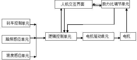
[0033] The logic control unit simultaneously detects whether there are signals from the brake control unit, cadence sensing unit, and slope sensing unit. If it is detected that the brake control unit has a brake signal, no matter whether there is a signal from the cadence sensing unit and the gradient sensing unit, a stop command will be output to the motor drive unit, and the motor cannot rotate.

Embodiment 2

[0034] Example 2: Static state

[0035]The logic control unit detects the brake control unit, if there is no brake signal, and the cadence sensing unit has no speed signal, then no matter whether there is a signal from the slope sensing unit, the logic control unit will regard the vehicle as not willing to start, and the logic control unit will output stop at this time Instructions are given to the motor drive unit, and the motor cannot rotate in any way.

Embodiment 3

[0036] Example 3: Riding on flat roads

[0037] The logic control unit detects the cadence sensing unit, there is a signal, the brake control unit has no signal, the slope sensing unit has a signal, and the logic control unit calculates that there is no slope, indicating that the vehicle has been started manually and is driving on a flat road. The control unit calls the default standard driving function, and drives the motor through the motor drive unit to generate torque, so that the whole vehicle is in power-assisted riding. The motor collects the cadence signal sent by the cadence sensing unit in real time through the logic control unit, and judges the driving parameters required by the motor; at the same time, the real-time state of the motor is fed back to the logic control unit by the assist ratio adjustment unit to judge whether the state of the motor has reached the desired value. state required.


PUM


Abstract

The invention relates to an electric power bicycle driving system capable of recognizing the state of a road. The electric power bicycle driving system comprises a brake control unit, a cadence sensing unit, a gradient sensing unit, a human-computer interaction interface, a logic control unit, a motor driving unit, a motor and a power rate regulating unit. The brake control unit, the cadence sensing unit and the gradient sensing unit are connected to the logic control unit respectively, the logic control unit is connected to the motor driving unit, the power rate regulating unit and the human-computer interaction interface respectively, the motor is simultaneously connected with the motor driving unit and the power rate regulating unit, and the power rate regulating unit is connected with the human-computer interaction interface at the same time. The logic control unit and the human-computer interaction interface mutually conduct feedback regulation, and the human-computer interaction interface and the power rate regulating unit mutually conduct feedback regulation. According to the electric power bicycle driving system, the power rate of the motor can be regulated by manually regulating a control button of the human-computer interaction interface, the gradient of the road can be also monitored at any time through the gradient sensing unit, the power rate of the motor can be increased or decreased according to uphill or downhill, and therefore a cyclist is always in a comfortable state.

Description

technical field [0001] The invention relates to an electric power-assisted bicycle drive system capable of identifying road surface conditions, and belongs to the field of electric power-assisted bicycle motor sensing induction control drive systems. Background technique [0002] Electric power-assisted bicycles, in the European Union, the United States, Canada, Japan and other countries, the law stipulates that they cannot be directly driven by electricity. It is not possible to directly start the motor with a switch without manual start. , and then use electric power to assist riding. Once the human power stops riding, the electric power also stops riding immediately. [0003] At present, the electric power-assisted bicycle drive system generally adopts two modes to judge whether the whole vehicle is started, one is to collect speed, and the other is to collect torque. The following are the descriptions of these two methods: [0004] (1) Acquisition of speed, the system c...

Claims


Application Information

Patent Timeline
IPC IPC(8): B62M6/45B62M6/50
Inventor 朱旭平孙敏丁强杨碧石蒋春李伟
Owner 孙敏
Why Eureka
Try Eureka