Roller conveying device

A conveying device and roller technology, applied in the directions of transportation, packaging, roller table, etc., can solve the problems of roller bending, trouble, equipment damage, etc., and achieve the effect of enhancing stability, avoiding bending or loosening of bolts, and simple structure

Inactive Publication Date: 2013-12-11
陈学军
View PDF5 Cites 2 Cited by
  • Summary
  • Abstract
  • Description
  • Claims
  • Application Information

AI Technical Summary

Problems solved by technology

[0002] Most of the existing roller transmissions use the rollers to be fixed on the holes with bolts. Such a connection method is relatively fixed, and a wrench is required for installation and disassembly, which is troublesome. In addition, when conveying heavy objects, high-intensity pressure may often cause the rollers to break. bending, causing equipment damage

Method used


Image

  • Roller conveying device
  • Roller conveying device

Examples


Embodiment Construction

[0012] In order to make the technical means, creative features, goals and effects achieved by the present invention easy to understand, the present invention will be further described below in conjunction with specific illustrations.

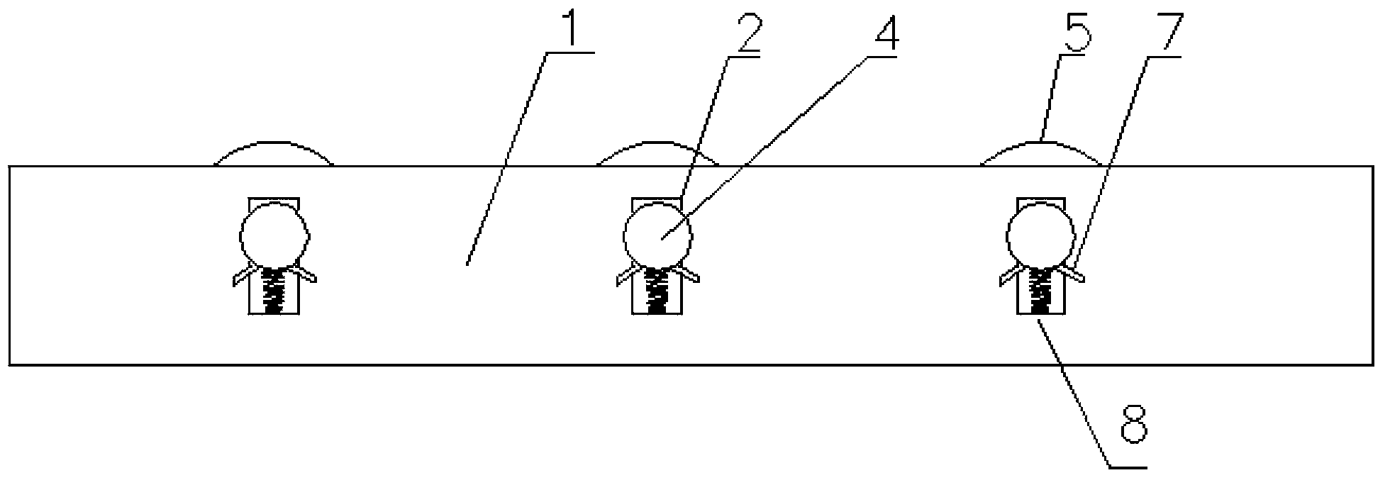
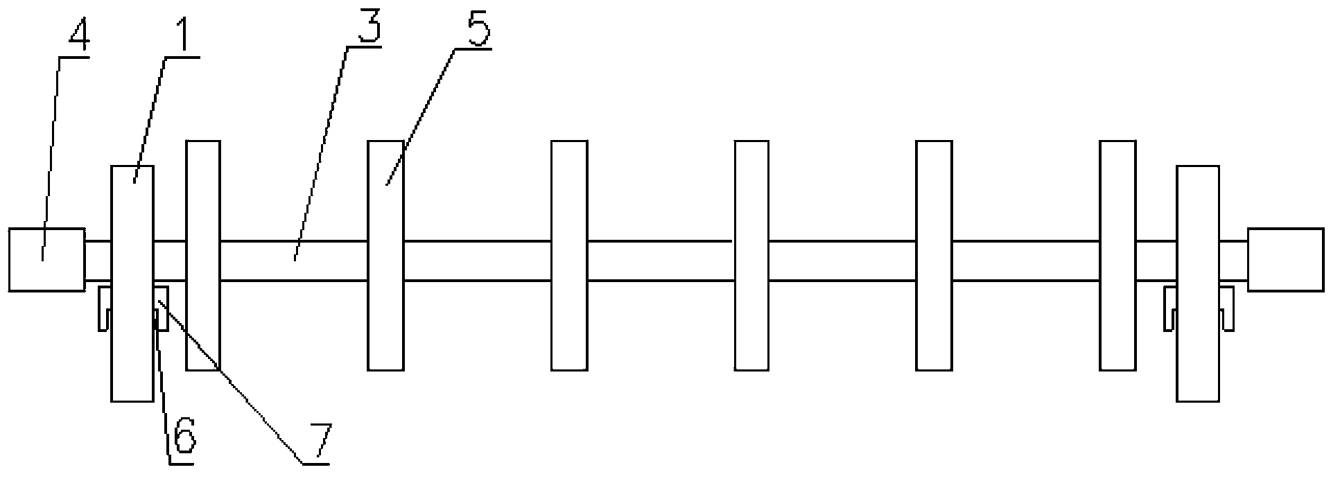
[0013] Such as figure 1 and figure 2 The roller conveying device shown includes brackets 1 on both sides. Vertical slots 2 are arranged on the brackets 1 on both sides. Rollers 3 are inserted in the vertical slots 2 on both sides. The two ends of the rollers 3 are covered with There is a protective cover 4, and the diameter of the protective cover 4 is larger than the width of the vertical long hole 2. The roller 3 is provided with a roller 5, wherein the vertical long hole 2 is provided with an arched plate 7 with slots 6 on both sides. The plate 7 is arched upwards, the roller 3 rests on the arc-shaped plate 7, and a spring 8 is fixedly welded on the bottom 7 of the arc-shaped plate, and the spring 8 is supported on the vertical slot 2.

[...


PUM


Abstract

The invention discloses a roller conveying device, and relates to a conveying device. The roller conveying device comprises two side brackets, wherein vertical slotted holes are formed in the two side brackets; a rolling shaft is inserted into the vertical slotted holes in the two sides; rollers are arranged on the rolling shaft; arched plates are arranged in the vertical slotted holes, and slots are formed in the two sides of the arched plates; the arched plates are upwards arched; the rolling shaft is arranged on the arched plates. The roller conveying device is simple in structure and reasonable in design; the conventional bolt connection fixing mode is replaced, so that the roller conveying device is more convenient to mount and dismount; moreover, a vibration cushioning effect can also be achieved through the arched plates, so that a descending space for the rolling shaft is provided, the rolling shaft can be prevented from being bent or bolts can be prevented from being loosened by long-term high pressure, and the structural stability is enhanced.

Description

Technical field: [0001] The invention relates to a conveying device, in particular to a roller conveying device. Background technique: [0002] Most of the existing roller transmissions use the rollers to be fixed on the holes with bolts. Such a connection method is relatively fixed, and a wrench is required for installation and disassembly, which is troublesome. In addition, when conveying heavy objects, high-intensity pressure may often cause the rollers to break. bend, causing equipment damage. Invention content: [0003] The technical problem to be solved by the present invention is to overcome the defects of the prior art and provide a roller conveying device with a simple structure and good shock-absorbing effect. [0004] The technical problem to be solved by the present invention is realized by the following technical solutions. [0005] A roller transmission device, characterized in that: it includes brackets on both sides, vertical slots are arranged on the bra...

Claims


Application Information

Patent Timeline
Patent Type & Authority Applications(China)
IPC IPC(8): B65G13/11
Inventor 陈学军
Owner 陈学军
Why Eureka
Try Eureka