Yield-increasing and energy-saving technology of carbon dioxide stripping urea and equipment of carbon dioxide stripping urea

A carbon dioxide and energy-saving equipment technology, which is applied in the field of urea medium-pressure decomposition and absorption and vacuum pre-concentration, can solve the problems that methylammonium liquid cannot be distributed to form a film, the corrosion of equipment is intensified, and the stripping efficiency is reduced, so as to solve the problem of insufficient urea production capacity, production The effect of efficiency improvement and urea production capacity improvement

Active Publication Date: 2013-12-11
BEIJING UNITY ENG
View PDF5 Cites 18 Cited by
  • Summary
  • Abstract
  • Description
  • Claims
  • Application Information

AI Technical Summary

Benefits of technology

This invention relates to improving the process for producing chemical products from CO2 gas without consuming too much power or generating excessive greenhouse gases during their manufacture. By utilizing these techniques, it becomes possible to produce higher amounts of urease per kilogram of material compared with traditional methods that require high pressures and large facilities. Additionally, there has been an improvement on concentration heat recover systems used together with other processes like evaporation/distillation columns. Overall, this innovative method allows for efficient use of resources while reducing environmental impact.

Problems solved by technology

The technical problem addressed in this patented method relating to producing urethane from nitride compounds involves controlling the amount of hydrogen cyanate formed during decomposition reactions between two chemical substances at different temperatures or pressures. This can affect how much more energy needs to produce each molecule of urethanum acid ester before decompositing into other products such as melamine. Additionally, there are limitations on achieving efficient separation due to factors like vapor pressure variations caused by temperature changes and impurities present within the mixture's composition.

Method used


Image

  • Yield-increasing and energy-saving technology of carbon dioxide stripping urea and equipment of carbon dioxide stripping urea
  • Yield-increasing and energy-saving technology of carbon dioxide stripping urea and equipment of carbon dioxide stripping urea
  • Yield-increasing and energy-saving technology of carbon dioxide stripping urea and equipment of carbon dioxide stripping urea

Examples


Embodiment Construction

[0025] The specific embodiments of the present invention will be further described in detail below in conjunction with the accompanying drawings.

[0026] In order to achieve the above object, the technical solution of the present invention is achieved in this way.

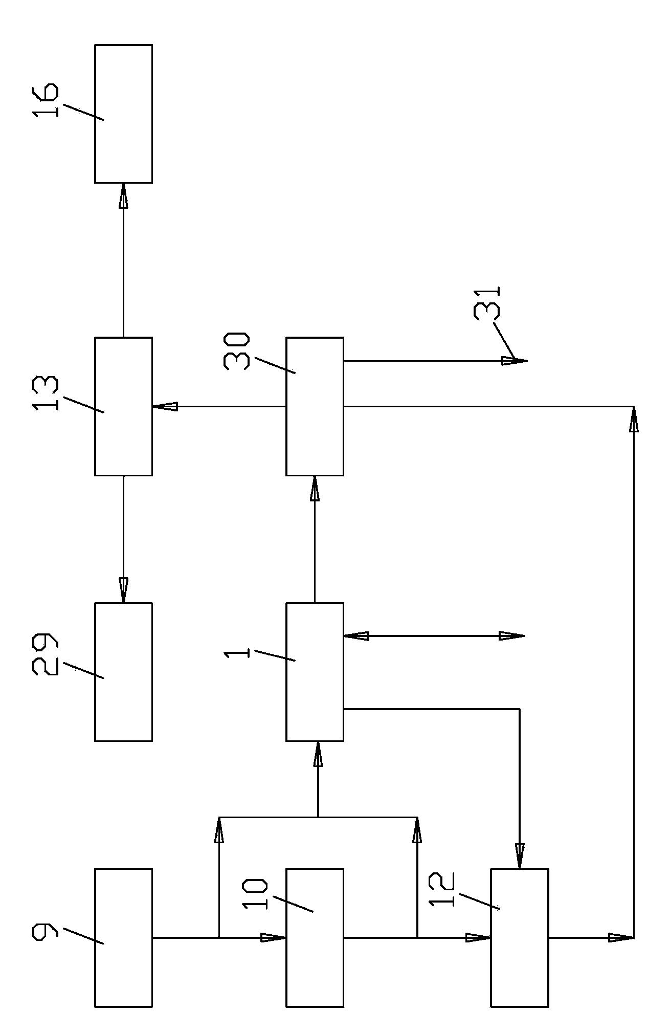
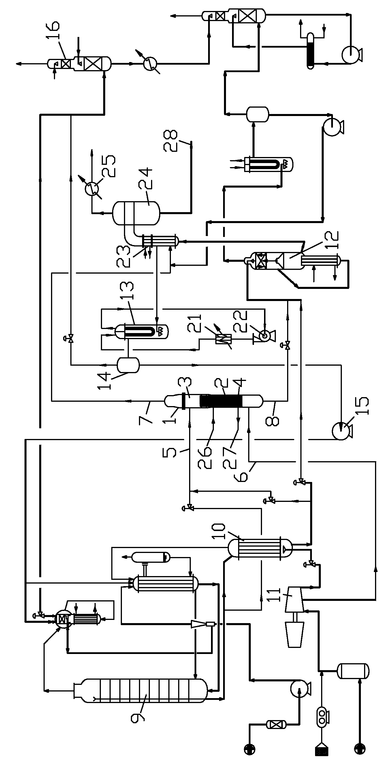
[0027] Such as figure 1 As shown, the production-increasing and energy-saving technology of carbon dioxide stripping urea involved in the present invention is carried out in the following steps.

[0028] .A. The urea reaction liquid from synthesis tower 9 with a temperature of 180~185°C and a pressure of 14.0~14.2MPa (G) is divided into two parts, most of which urine is sent to high-pressure stripper 10 for equal pressure stripping and decomposition, about 1 / 3 of the stripped urine is decompressed to 1.7~2.0MPa(G), and a small part of the bottom liquid of the synthetic tower 9 is directly decompressed to 1.7~2.0MPa(G). Pressure stripping decomposition tower 1 carries out stripping and decomposition.

[0029] B....


PUM


Abstract

The invention relates to a yield-increasing and energy-saving technology of carbon dioxide stripping urea and equipment of the carbon dioxide stripping urea. A medium-pressure decomposition and absorption technology, a vacuum heat recovery technology and a medium-pressure decomposition and absorption system are adopted additionally; two-section evaporation is changed to three-section evaporation; a rectifying section is arranged at the upper part of a medium-pressure stripping decomposition tower; a heating section is arranged at the lower part of the medium-pressure stripping decomposition tower; lower liquid of a synthetic tower and discharge liquid of a stripping tower are subjected to pressure reduction convergence, and then enter the medium-pressure stripping decomposition tower; urea methylamine liquid is in countercurrent contact with decomposition gas at the rectifying section, is rectified and then enters a heating section tube pass to urge methylamine to be decomposed into carbon dioxide and ammonia; a housing side is heated by steam of 185-195 DEG C, and then enters a medium-pressure methylamine condenser to be condensed; and the urea methylamine liquid at the bottom of the tower enters a urea rectifying tower to be further decomposed. With the adoption of the scheme, the yield-increase difficulty of the carbon dioxide stripping urea is overcome; the productivity of the urea can be improved greatly; an energy consumption index is reduced correspondingly; the problem of a nitrogenous fertilizer enterprise that the productivity of the urea is insufficient after a yield of synthesis ammonia is increased is solved better; and the productivity of the urea can be improved by above 50%.

Description


Claims


Application Information

Patent Timeline
Owner BEIJING UNITY ENG
Why Eureka
Try Eureka