Steel die and reinforced concrete integrated combination beam structure

An integrated, composite beam technology, applied in the direction of structural elements, elongated structural members for load-bearing, bridges, etc., can solve the problems of high construction cost, low progress and efficiency, occupying a large prefabricated site, etc., and achieve low cost. , The construction progress is simplified and the construction is fast.

Active Publication Date: 2013-12-11
ZHEJIANG CTB WAVEFORM STEEL WEB
View PDF5 Cites 6 Cited by
  • Summary
  • Abstract
  • Description
  • Claims
  • Application Information

AI Technical Summary

Problems solved by technology

[0003] The present invention is aimed at the beams in bridges and buildings in the prior art, using prefabricated or molded cast-in-place construction, the transportation and hoisting of prefabricated beams is very heavy, and requires a large amount of prefabricated space, and the cast-in-place beams need a lot of formwork and labor. Due to the disadvantages of high construction cost, low progress and low efficiency, a beam structure with light weight, fast construction and low cost is provided.

Method used


Image

  • Steel die and reinforced concrete integrated combination beam structure
  • Steel die and reinforced concrete integrated combination beam structure
  • Steel die and reinforced concrete integrated combination beam structure

Examples


Embodiment 1

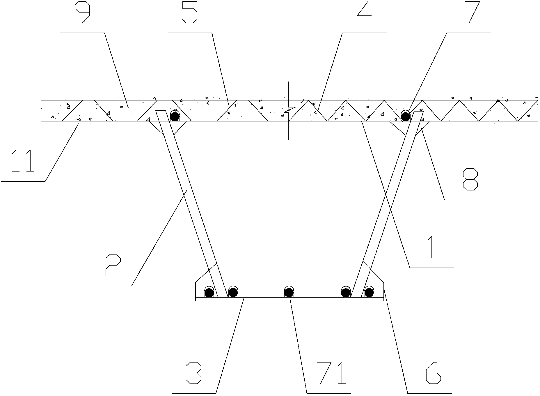
[0025] Steel mold steel concrete integrated composite beam structure, such as figure 1 , 3 , 4, including steel top plate 1, steel bottom plate 3, corrugated steel plate 2, described corrugated steel plate 2 connects steel top plate 1 and steel bottom plate 3, pours reinforced concrete 9 on steel top plate 1, and steel top plate 1 is arranged on corrugated steel plate 2 The corrugated steel plate 2 is inserted into the reinforced concrete 9 through the steel top plate 1 on both sides. The steel top plate 1 and the corrugated steel plate 2 are respectively provided with pegs.

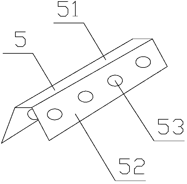
[0026] The steel top plate 1 is provided with a micro-strain wave 11, the micro-strain wave 11 is a micro-strain wave with a convex crest, and the wave height of the micro-strain wave 11 is less than 3-20 times of the thickness of the steel top plate 1, and the micro-strain wave 11 The distance between adjacent wave crests is greater than 500 mm; the steel base plate 3 is provided with a micro strain w...

Embodiment 2

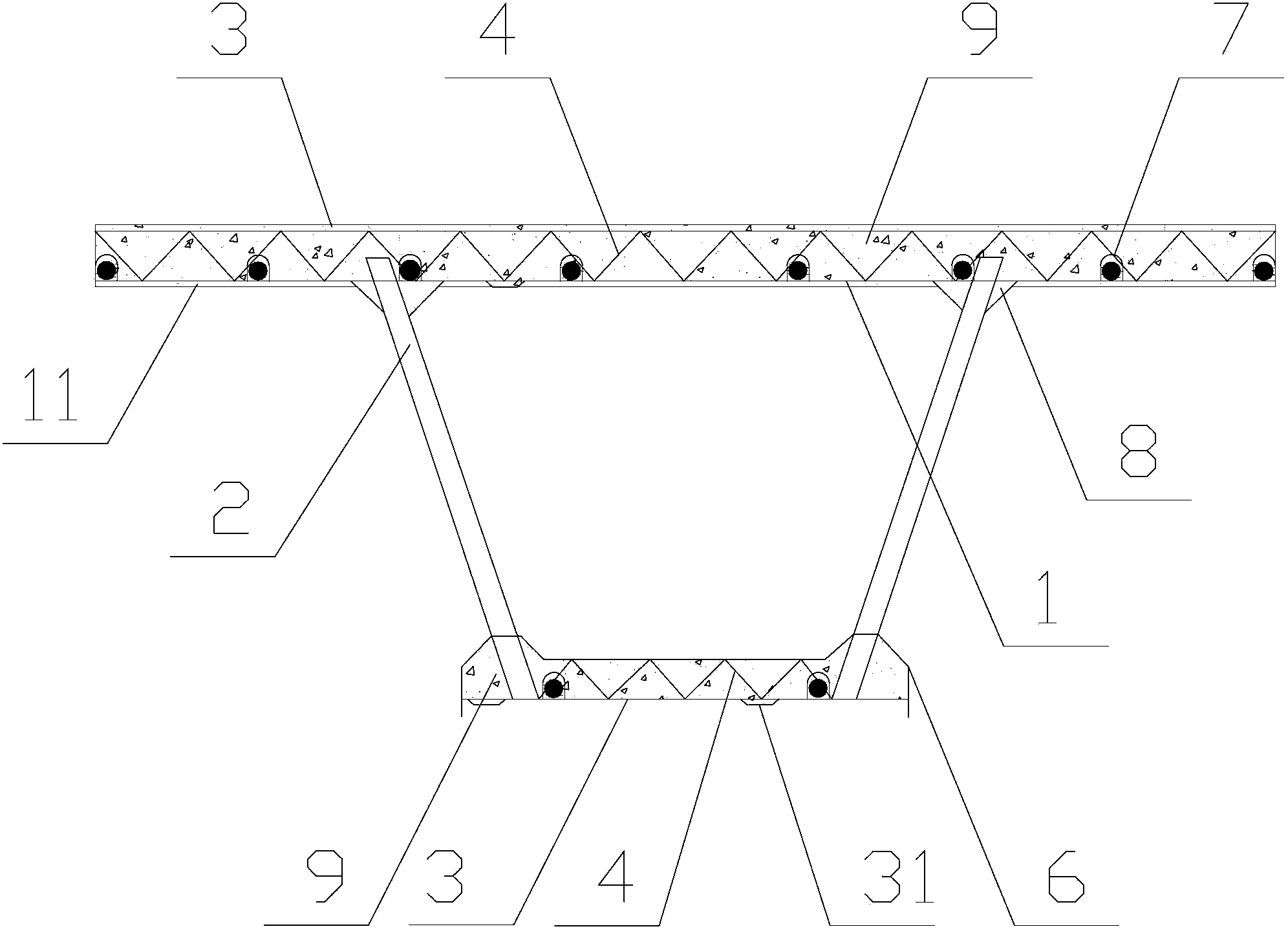
[0033] Steel mold steel concrete integrated composite beam structure, such as figure 2 , 3 , 4, including steel top plate 1, steel bottom plate 3, corrugated steel plate 2, described corrugated steel plate 2 connects steel top plate 1 and steel bottom plate 3, pours reinforced concrete 9 on steel top plate 1, and steel top plate 1 is arranged on corrugated steel plate 2 The corrugated steel plate 2 is inserted into the reinforced concrete 9 through the steel top plate 1 on both sides. The steel top plate 1 and the corrugated steel plate 2 are respectively provided with pegs.

[0034] The corrugated steel plate 2 is welded to the steel base plate 3, and the steel base plate 3 is poured with reinforced concrete 9.

[0035]The steel top plate 1 is provided with a micro-strain wave 11, the micro-strain wave 11 is a micro-strain wave with a convex crest, and the wave height of the micro-strain wave 11 is less than 3-20 times of the thickness of the steel top plate 1, and the mic...


PUM


Abstract

The invention relates to a combination beam structure, and discloses a steel die and reinforced concrete integrated combination beam structure. The steel die and reinforced concrete integrated combination beam structure comprises a steel top board (1), steel baseboards (3) and corrugated steel sheets (2), the corrugated steel sheets (2) are connected with the steel top board (1) and the steel baseboards (3), reinforced concrete (9) is poured on the steel top board (1), the steel top board (1) is arranged at two sides of the corrugated steel sheets (2), and the corrugated steel sheets (2) traverse through the steel top board (1) and then are inserted into the reinforced concrete (9). The lightweight steel die and reinforced concrete integrated structure adopting the corrugated steel sheet as an anti-shear structure, the support type steel sheet as a steel die and combination structure duplicate member, a steel bar skeleton or corrugated porous sheet as an anti-blend member, micro-stress waves as a concrete shrink creeping strain measure and a prestress external or internal steel rope or high-strength steel bar as a tensile member avoid traditional wet joints, and has the advantages of good transverse force transmission, light weight, fast construction and low cost.

Description

technical field [0001] The invention relates to a composite beam structure, in particular to a steel mold steel concrete integrated composite beam structure. Background technique [0002] At present, light structure and convenient construction have always been the goals of the engineering industry. Most of the beams in existing bridges and buildings are prefabricated or molded and cast-in-place. The transportation and hoisting of prefabricated beams are very heavy and require A large number of prefabricated sites and cast-in-place beams require a lot of formwork and labor. The above-mentioned construction costs, progress, and efficiency are all low. How to develop a light-weight, fast-construction, and low-cost beam structure has always been the subject of industry dreams. Contents of the invention [0003] The present invention is aimed at the beams in bridges and buildings in the prior art, using prefabricated or molded cast-in-place construction, the transportation and ...

Claims


Application Information

Patent Timeline
Patent Type & Authority Applications(China)
IPC IPC(8): E04C3/293E01D19/00
Inventor 孙天明张小东
Owner ZHEJIANG CTB WAVEFORM STEEL WEB
Why Eureka
Try Eureka