Pantograph damper damping throttling device

A throttling device and damper technology, applied in the direction of shock absorber, shock absorber, spring/shock absorber, etc., can solve the problem that the damping force cannot be adjusted and controlled arbitrarily, and achieve stable power supply and stable resistance. and features, creative and unique effects

Active Publication Date: 2013-12-11
ZHUZHOU CSR TIMES ELECTRIC CO LTD
View PDF5 Cites 12 Cited by
  • Summary
  • Abstract
  • Description
  • Claims
  • Application Information

AI Technical Summary

Problems solved by technology

[0004] In view of this, the object of the present invention is to provide a pantograph damper damping throttling device, which overcomes the pr

Method used


Image

  • Pantograph damper damping throttling device
  • Pantograph damper damping throttling device
  • Pantograph damper damping throttling device

Examples


Embodiment Construction

[0025] In order to make the purpose, technical solutions and advantages of the embodiments of the present invention clearer, the technical solutions in the embodiments of the present invention will be clearly and completely described below in conjunction with the drawings in the embodiments of the present invention. Obviously, the described embodiments It is only some embodiments of the present invention, but not all embodiments. Based on the embodiments of the present invention, all other embodiments obtained by persons of ordinary skill in the art without creative efforts fall within the protection scope of the present invention.

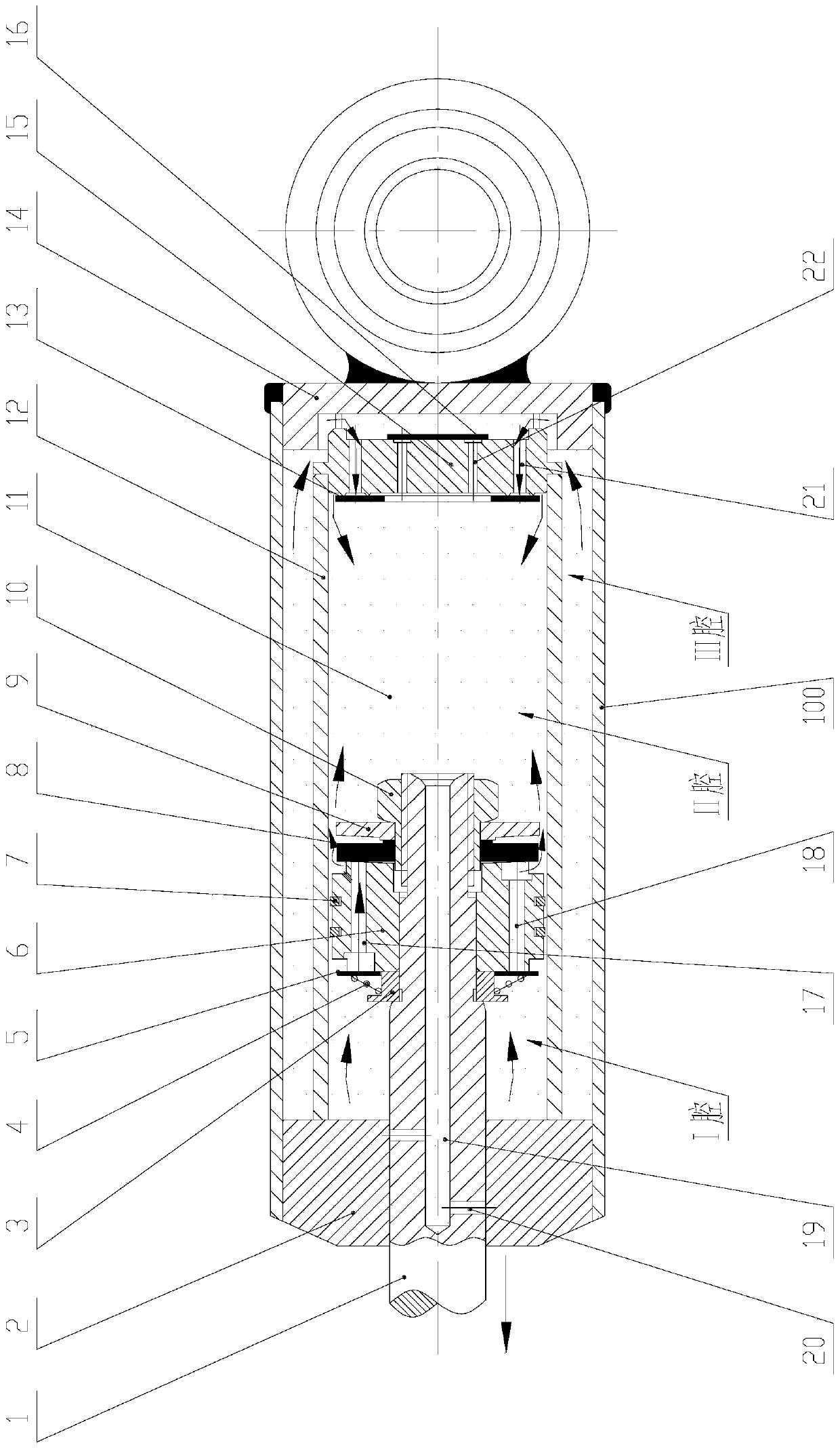
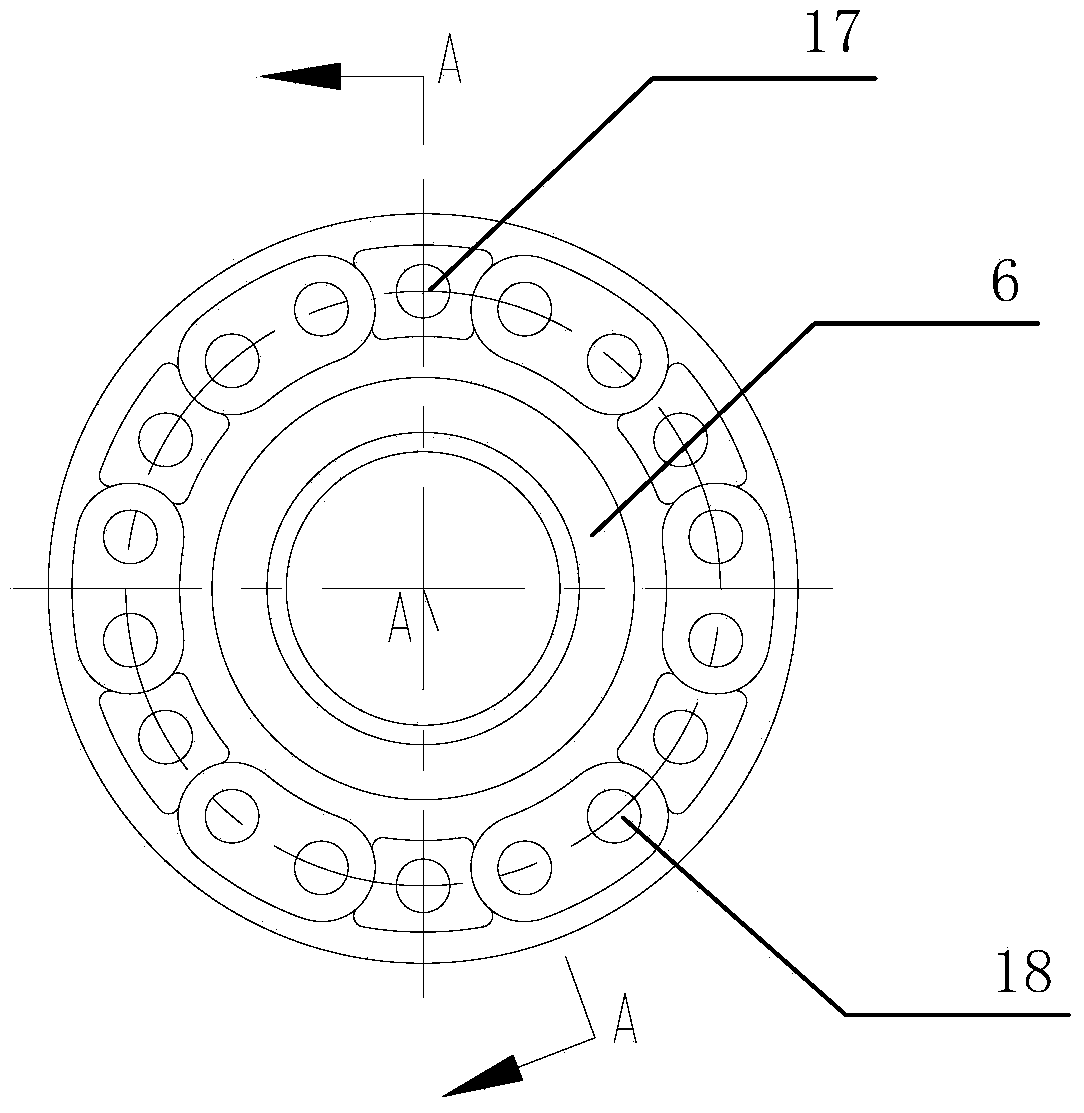
[0026] as attached figure 2 , attached image 3 And attached Figure 4 As shown, a specific embodiment of a pantograph damper damping throttling device of the present invention is given, and the present invention will be further described below in conjunction with the drawings and specific embodiments.

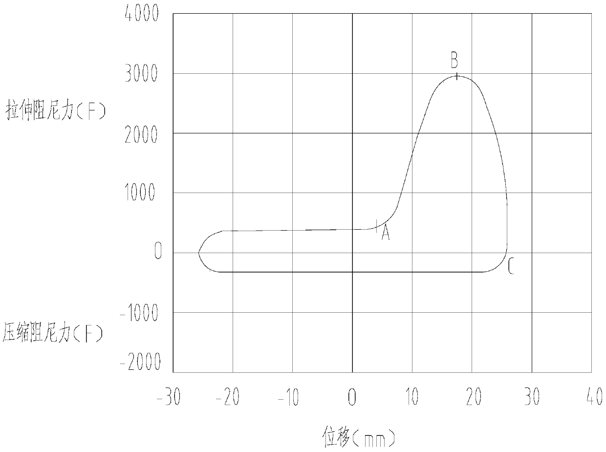
[0027] as attached figure 1Shown is th...


PUM

PropertyMeasurementUnit
Taperaaaaaaaaaa

Abstract

The invention discloses a pantograph damper damping throttling device. One end of an oil cylinder is sealed through a guide bearing. A center hole is formed in the guide bearing which provides supporting and guiding for a piston rod. The other end of the oil cylinder is sealed through a bottom valve seat. A piston, a spring base, springs, a compression valve plate, an stretchable spring valve plate and a stop plate are installed on the piston rod. The oil cylinder is divided into a first cavity and a second cavity through the piston. Stretchable throttling holes and compression throttling holes are formed in the piston, wherein the stretchable throttling holes and the compression throttling holes are oppositely arranged. The compression valve plate located at the position, close to the end face of one side of the first cavity of the oil cylinder, of the piston covers the compression throttling holes and is pressed through the springs, and the springs are fixed on the spring base. The stretchable spring valve plate located at the position, close to the end face of one side of the second cavity of the oil cylinder, of the piston covers the stretchable throttling holes and is pressed through the stop plate, and the stop plate is fixed on the piston rod through a locking nut. The pantograph damper damping throttling device can overcome the technical defect that in the prior art, when the piston rod is stretched to the final stroke, damping force can not be adjusted and controlled at will.

Description

technical field [0001] The invention relates to a damping adjustment device, in particular to a pantograph damper damping throttling device applied to pantographs of rail transit vehicles such as electric locomotives and subway trains. Background technique [0002] The pantograph is an electrical component used to absorb energy from the catenary on rail vehicles such as electric locomotives and subway trains. It is a articulated mechanical component. It is installed on the roof of rail transit vehicles through insulators. After the pantograph head is raised, it collects current from the catenary, and transmits the current to the vehicle for use by the locomotive. The pantograph and its attached installation parts usually include: damper, bottom frame, bow lifting device, lower arm, bow assembly, lower guide rod, upper arm, upper guide rod, bow head and slide plate, and the damper is installed on the bottom frame and between the lower arms. The damper is an important part o...

Claims


Application Information

Patent Timeline
IPC IPC(8): F16F9/24F16F9/34F16F9/50
Inventor 曾松林黎剑锋殷盛福王凯平熊求颛陈永军向贤虎
Owner ZHUZHOU CSR TIMES ELECTRIC CO LTD
Why Eureka
Try Eureka