Novel hydraulic type inerter damping device

A shock absorber and hydraulic technology, applied in the direction of shock absorber, liquid shock absorber, spring/shock absorber, etc., can solve the problem of increased damping force, achieve the effect of improving shock absorbing performance and weakening the coupling effect

Active Publication Date: 2022-02-11
GUANGZHOU UNIVERSITY
View PDF14 Cites 0 Cited by
  • Summary
  • Abstract
  • Description
  • Claims
  • Application Information

AI Technical Summary

Problems solved by technology

[0002] In the hydraulic inertial element, the liquid rotates and flows in the return pipe, which not only generates inertial force, but also generates damping force. In order to obtain a larger inertial force, the cross section of the return pipe is usually reduced, but the damping force will increase significantly. Large, covering the effect of inertial force, the coupling effect of this inertial force and damping force greatly limits the application of hydraulic inertial components

Method used


Image

  • Novel hydraulic type inerter damping device
  • Novel hydraulic type inerter damping device
  • Novel hydraulic type inerter damping device

Examples


Embodiment 1

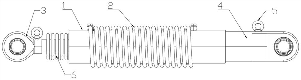
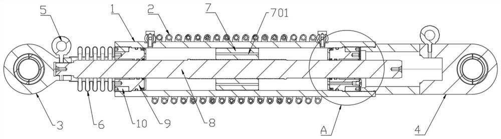
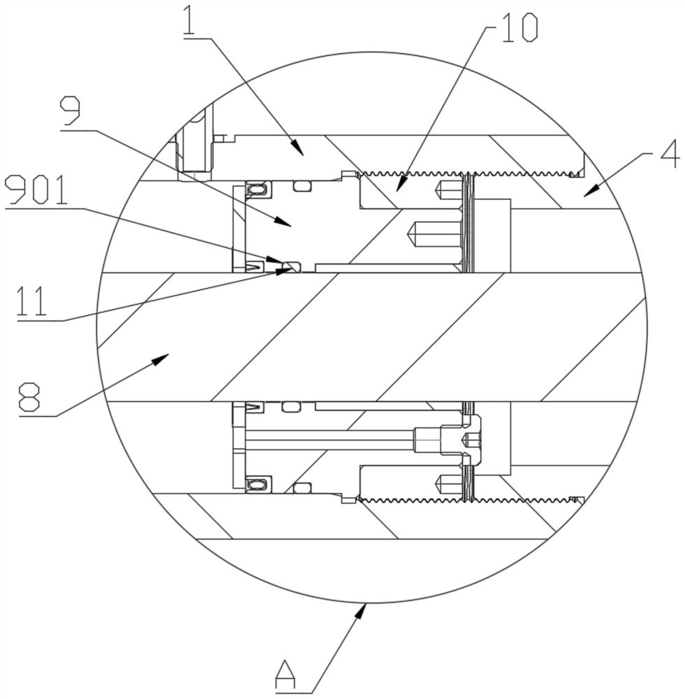
[0025] Such as Figure 1 ~ Figure 4 As shown, a new type of hydraulic inertial shock absorber includes a hydraulic cylinder 1, both ends of the hydraulic cylinder 1 are provided with sealing sleeves 9, and the outer side of the sealing sleeve 9 is equipped with a fastening ring 10, and the fastening ring 10 It is screwed and connected with the inner wall of the hydraulic cylinder 1. The sealing sleeve 9 is fixed in the hydraulic cylinder 1 through the fastening ring 10. The piston rod 8 is inserted into the hydraulic cylinder 1. The piston rod 8 is connected with the hydraulic cylinder 1 through two sealing sleeves 9. The diameter of the two ends of the piston rod 8 is the same as the inner diameter of the sealing sleeve 9, and the inner wall of the sealing sleeve 9 is provided with a sealing groove 901, and a sealing rubber ring 11 is fixedly installed in the sealing groove 901 to prevent leakage. There is a piston 7 in the liquid cylinder 1, the piston 7 is fixedly connected...


PUM


Abstract

The invention provides a novel hydraulic type inerter damping device, a piston is in clearance fit with a hydraulic cylinder, through holes are formed in the piston, and when the damping device works, part of working liquid flows into the working space on the other side of the piston through the clearance between the piston and the hydraulic cylinder and the through hole in the piston; non-linear damping force with a low speed index is generated by flowing of the working liquid, overlarge damping output can be limited, and the device is effectively protected. A ball and a plugging ball are arranged in a spiral return pipe communicated with the hydraulic cylinder, the other part of liquid rotates along the spiral return pipe, the ball and the plugging ball roll in a reciprocating mode under the action of pressure difference, and the mass amplification effect can be achieved through the conversion mode from linear motion of the piston to rotating motion of working liquid. The inertia force is improved, meanwhile, the coupling effect of the damping force and the inertia force in the spiral return pipe is weakened, the damping performance is improved, and dimethyl silicone oil is adopted as working liquid so that the damping output level can be increased.

Description

technical field [0001] The invention relates to the technical field of building damping control, in particular to a novel hydraulic inertial capacity damping device. Background technique [0002] In the hydraulic inertial element, the liquid rotates and flows in the return pipe, which not only generates inertial force, but also generates damping force. In order to obtain a larger inertial force, the cross section of the return pipe is usually reduced, but the damping force will increase significantly. The coupling effect of this inertial force and damping force greatly limits the application of hydraulic inertial components. Contents of the invention [0003] The purpose of the present invention is to provide a new type of hydraulic inertial shock absorber, which can increase the inertial force and reduce the damping force in the return pipe by filling steel balls in the return pipe, thus weakening the inertia and damping. coupling effect. [0004] The invention provides...

Claims


Application Information

Patent Timeline
Patent Type & Authority Applications(China)
IPC IPC(8): F16F9/18F16F9/32F16F9/44
CPCF16F9/18F16F9/32F16F9/44F16F7/1034Y02E60/16
Inventor 陈华霆黄景晖刘彦辉周福霖
Owner GUANGZHOU UNIVERSITY
Why Eureka
Try Eureka