Method for processing butterfly plate device of butterfly valve body

A butterfly valve and butterfly valve technology, which is applied in the processing field of butterfly valve body and disc device, can solve the problems of empty shaft rotation, damage and breakage, and achieve the effect of prolonging service life and reducing water leakage points and sliding pins.

Inactive Publication Date: 2013-12-11
夏许超
View PDF5 Cites 6 Cited by
  • Summary
  • Abstract
  • Description
  • Claims
  • Application Information

AI Technical Summary

Problems solved by technology

[0002] The original butterfly plate and valve stem are separated, and there is a reserved hole in the middle of the butterfly plate. Most of the valve stems are round rods. Then drill a hole and hit the fixing pin to connect the valve stem and the butterfly plate. Once the fixing pin is damaged after long-term use, it will cause the empty shaft to rotate.
When the butterfly plate is cast, there must be reserved holes to ensure the centrality of the machining. If there is an error, it will cause uneven force on the left and right after the butterfly plate is installed, and the butterfly plate will be broken under pressure.
To match the butterfly plate with the valve stem, the valve stem should be inserted into the center hole of the butterfly plate and the fixing pin should be drilled. There will also be leakage from the fixing pin.

Method used


Image

  • Method for processing butterfly plate device of butterfly valve body
  • Method for processing butterfly plate device of butterfly valve body

Examples


Embodiment 1

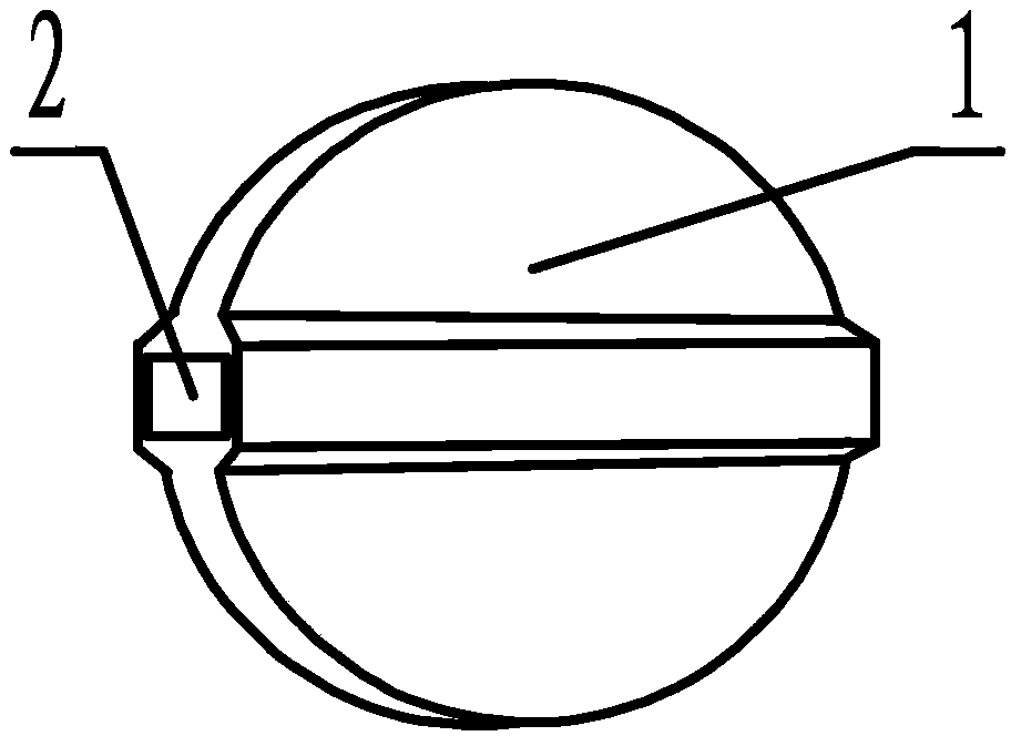
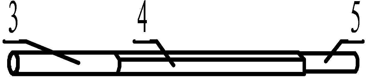
[0015] As shown in the figure; the center line of the butterfly plate 1 is provided with a radially concentric rectangular butterfly plate shaft hole 2; the connecting plate shaft section 4 is set in the rectangular butterfly plate shaft hole 2; the butterfly valve stem is coaxially set into three sections, and the main shaft section 3 The connecting plate shaft section 4 is arranged on one side, and the connecting plate shaft section 4 is rectangular.

Embodiment 2

[0017] Install the mold on the punching machine, place the original steel blank in the middle of the mold, punch it into the blank of the butterfly plate 1, take out the blank of the butterfly plate 1 from the mold, and fix the blank of the butterfly plate 1 radially on the drilling machine, and the drilling machine passes through The center line of the butterfly plate 1 radially drills a through-round hole, then removes the disc 1 with the through-round hole drilled, and fixes it radially to a milling machine, and the milling machine mills the through-round hole into a rectangular butterfly plate shaft hole 2.

Embodiment 3

[0019] The coaxial design of the butterfly valve stem is divided into three sections. On the lathe, the cylindrical steel is turned into a cylindrical main shaft section 3 and a connecting plate shaft section 4, a fixed shaft section 5, a cylindrical main shaft section 3 and a connecting plate shaft section 4 The diameter of the fixed shaft section 5 is larger than the diagonal length of the rectangle of the butterfly plate shaft hole 2; the diameter of the fixed shaft section 5 is smaller than the length of the straight side of the butterfly plate shaft hole 2 rectangle; The valve stem of the butterfly valve is fixed to the planer, and the shaft section 4 of the connecting plate is planed on the planer to make the stem of the cylindrical butterfly valve into a rectangle smaller than the shaft hole 2 of the butterfly plate; The connecting plate shaft section 4 can be installed in the butterfly plate shaft hole 2 correspondingly.


PUM


Abstract

The invention relates to a method for processing a butterfly plate device of a butterfly valve body. The butterfly plate device comprises a butterfly plate, a butterfly plate axle hole, a main shaft section, a connecting plate shaft section and a fixed shaft section, wherein butterfly plate is made by stamping or casting; the radial concentric rectangular butterfly plate axle hole is formed in the center line of the butterfly plate; the connecting plate shaft section is arranged in the rectangular butterfly plate axle hole; a valve rod of a butterfly valve is divided into three sections in a coaxial way; on a lathe, a cylindrical steel bar is turned into the cylindrical main shaft section and the connecting plate shaft section, and the diameter of the cylindrical steel car is larger than the diagonal length of the butterfly plate axle hole; the diameter of the fixed shaft section is smaller than the length of the rectangular straight side of the butterfly plate axle hole; the connecting plate shaft section is planed on the cylindrical valve rod of the butterfly valve, and the cylindrical valve rod of the butterfly valve is fixed on a planer; the valve rod of the butterfly valve is planed into a corresponding rectangle smaller than the butterfly plate axle hole and then is installed into the butterfly plate axle hole. The design is reasonable; the butterfly plate axle hole is designed into a square shape, the square connecting plate shaft section corresponds to the butterfly plate axle hole, and the valve rod is closely matched with the butterfly plate, so that a fixing pin is not needed for fixing, water leakage point positions and sliding pins which are caused during processing and manufacturing can be reduced, the butterfly plate device is firm and durable, and the service life is prolonged.

Description

technical field [0001] The invention relates to the processing of a valve device of a pipeline, in particular to a processing method of a butterfly plate device of a butterfly valve body. Background technique [0002] The original butterfly plate and valve stem are separated, and there is a reserved hole in the middle of the butterfly plate. Most of the valve stems are round rods. Then drill a hole and hit a fixing pin to connect the valve stem and the butterfly plate. Once the fixing pin is damaged after long-term use, it will cause the empty shaft to rotate. When the butterfly plate is cast, there must be reserved holes to ensure the centrality of the machining. If there is an error, it will cause uneven force on the left and right after the butterfly plate is installed, and the butterfly plate will be broken under pressure. The cooperation between the butterfly plate and the valve stem requires the valve stem to be inserted into the center hole of the butterfly plate and...

Claims


Application Information

Patent Timeline
Patent Type & Authority Applications(China)
IPC IPC(8): F16K1/48B23P15/00
Inventor 夏许超尚燕飞
Owner 夏许超
Why Eureka
Try Eureka