
Ultrahigh-temperature heat-insulation device

A heat insulation and heat preservation device technology, applied in the direction of heat preservation, pipeline protection through heat insulation, pipeline protection, etc., can solve the problems of not being able to play the role of heat preservation, and achieve the effect of simple structure, convenient use and installation

Active Publication Date: 2013-12-11
ZHEJIANG CHUANGXIANG ENERGY SAVING TECH
View PDF7 Cites 5 Cited by
  • Summary
  • Abstract
  • Description
  • Claims
  • Application Information

AI Technical Summary

Problems solved by technology

However, the above-mentioned thermal insulation measures are basically applicable to ordinary high-temperature equipment and high-temperature pipelines. The surface temperature of thermal equipment and pipelines exceeds what people call high temperatures, such as 100-200°C; but for temperatures of 300°C or even 600°C , it can be said to be ultra-high temperature. At this time, it is basically not suitable to use conventional fiber insulation materials for insulation, because the ultra-high temperature will burn these fiber insulation materials. It will also turn red under high temperature conditions. Therefore, under ultra-high temperature conditions, conventional inorganic or organic fiber insulation materials or vacuum or thickened material thickness cannot play a good insulation effect

Method used


Image

  • Ultrahigh-temperature heat-insulation device
  • Ultrahigh-temperature heat-insulation device

Examples


Embodiment Construction

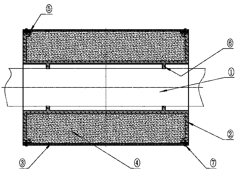
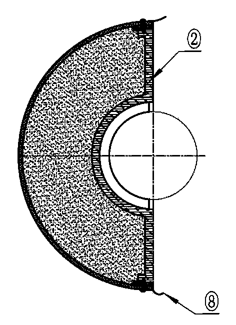
[0011] The present invention will be described in detail below in conjunction with accompanying drawing: figure 1 , 2 As shown, the thermal insulation device of the present invention is composed of a carbon-carbon material layer 2 attached to the surface of thermal equipment and pipeline 1, a high-temperature-resistant material layer 4 arranged in the middle, and an outer wall stainless steel layer 3. At least two thermal insulation pads 6 are arranged between the thermal equipment and the surface of the pipeline 1 to maintain the gap between the thermal equipment and the thermal insulation object (thermal equipment and pipeline).

[0012] The heat preservation device is composed of heat preservation blocks fixedly connected by buckles 8 or straps, and at least one section or part of the outer surface of the carbon material layer 2 of each heat preservation block is consistent with the outer surface of the thermal equipment and the pipeline 1, And an inner frame is formed, wh...


PUM


Abstract

Provided is an ultrahigh-temperature heat-insulation device. The ultrahigh-temperature heat-insulation device comprises a carbon-carbon material layer, a high-temperature-resisting material layer and an outer wall stainless steel layer, wherein the carbon-carbon material layer is arranged on the surface of a thermal device and the surface of a pipeline in an internally attached mode, the high-temperature-resisting material layer is arranged in the middle, and at least two heat insulation cushion blocks are arranged between the carbon-carbon material layer and the surface of the thermal device and pipeline. The ultrahigh-temperature heat-insulation device is formed by heat insulation blocks through hasps or binding bands in a fixed connection mode, at least one section or part of the surface, on the outer side of the carbon-carbon material layer, of each heat insulation block is consistent with the outer surface of the thermal device and pipeline, and is provided with an inner frame body which is filled with the high-temperature-resisting material layer, the outer wall stainless steel layer is fastened on the inner frame body through fasteners, the outer surface of the outer wall stainless steel layer is of a plane shape or an arc shape or a semi-circle shape, or the shape of the outer surface of the outer wall stainless steel layer is consistent with the shape of the surface of the outer side of the carbon-carbon material layer. The ultrahigh-temperature heat-insulation device has the advantages of being simple in structure, mainly applicable to effective heat preservation when the surface of the thermal device or the surface of the pipeline is in the ultra-temperature state with the temperature of more than 650DEG C, and the like.

Description

technical field [0001] The invention relates to an ultra-high temperature heat insulation device mainly used for pipelines or equipment, and belongs to the technical field of heat preservation. Background technique [0002] In order to save energy and reduce energy consumption, some thermal insulation measures are taken for some thermal equipment and thermal fluid transportation pipelines, and thermal insulation materials are used on the surface or pipeline of thermal equipment to reduce the heat dissipation and achieve the purpose of energy saving. However, the above-mentioned thermal insulation measures are basically applicable to ordinary high-temperature equipment and high-temperature pipelines. The surface temperature of thermal equipment and pipelines exceeds what people call high temperatures, such as 100-200°C; but for temperatures of 300°C or even 600°C , it can be said to be ultra-high temperature. At this time, it is basically not suitable to use conventio...

Claims


Application Information

Patent Timeline
IPC IPC(8): F16L59/12F16L59/04
Inventor 岑志超
Owner ZHEJIANG CHUANGXIANG ENERGY SAVING TECH
Learn More