LED lamp and circuit connecting method thereof

A LED lamp and electrical connection technology, applied in printed circuit, circuit layout, printed circuit manufacturing, etc., can solve the problems of easy false welding, difficult welding, scratches and damage of wire metal substrate, etc., to avoid false welding and avoid scratches The effect that wound damage, welding are easy

Inactive Publication Date: 2013-12-11
ZHEJIANG SHENGHUI LIGHTING
View PDF3 Cites 9 Cited by
  • Summary
  • Abstract
  • Description
  • Claims
  • Application Information

AI Technical Summary

Problems solved by technology

[0003] In the prior art, wires are generally used to connect the power supply device and the metal substrate together by manual welding. However, manual welding is used, because the metal substrate dissipates heat well, and the welding time is not easy to control, and it is easy to false and false welds; in addition, The wire is easily scratched and damaged by the metal substrate, resulting in a short circuit; and it is not easy to solder because it needs to be artificially fixed after the wire is welded.

Method used


Image

  • LED lamp and circuit connecting method thereof
  • LED lamp and circuit connecting method thereof
  • LED lamp and circuit connecting method thereof

Examples


Embodiment 1

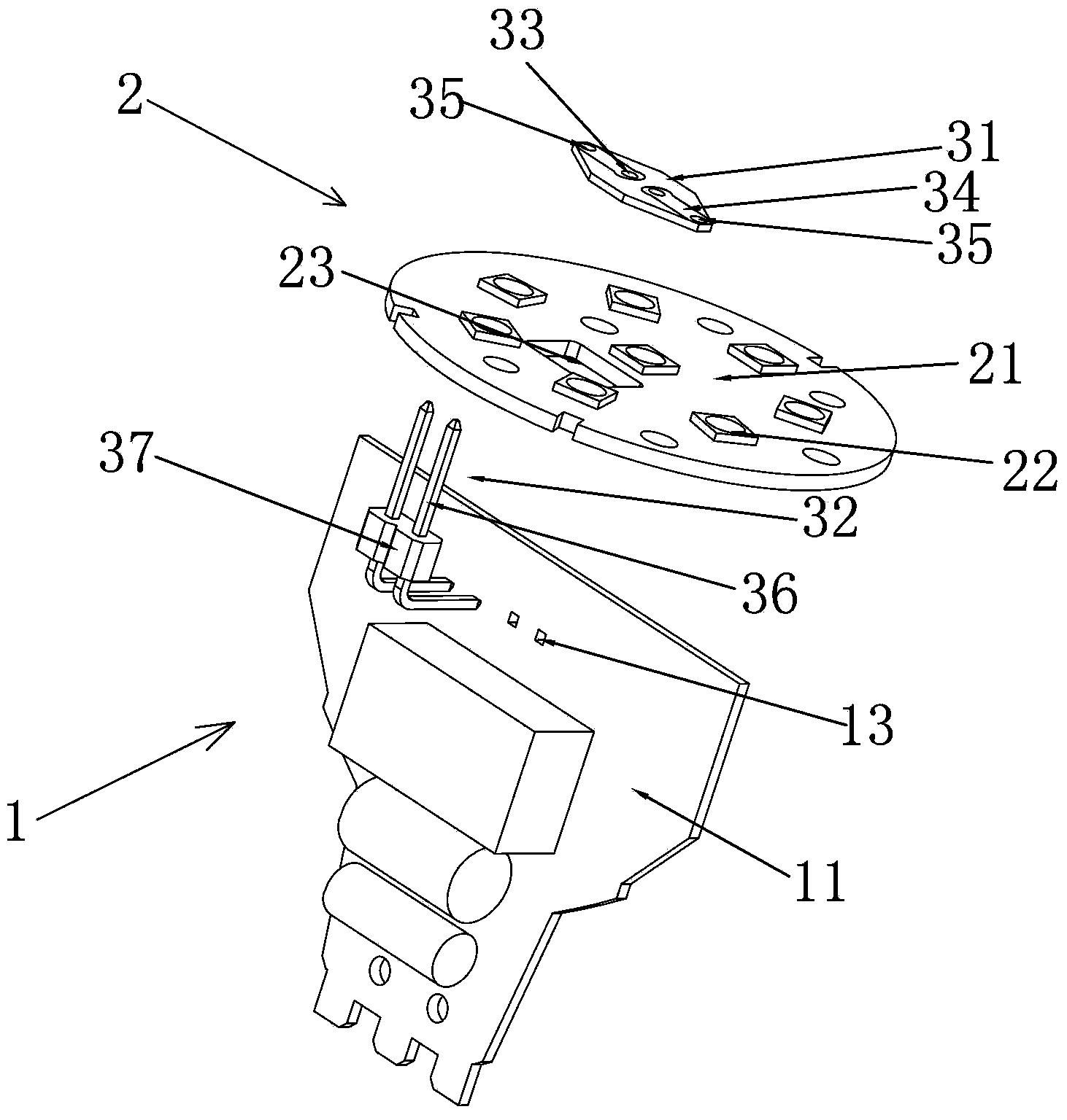
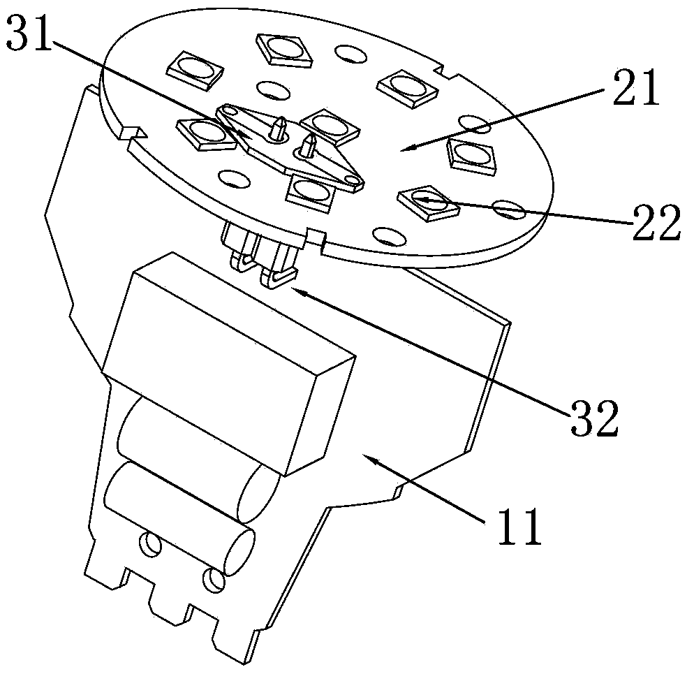
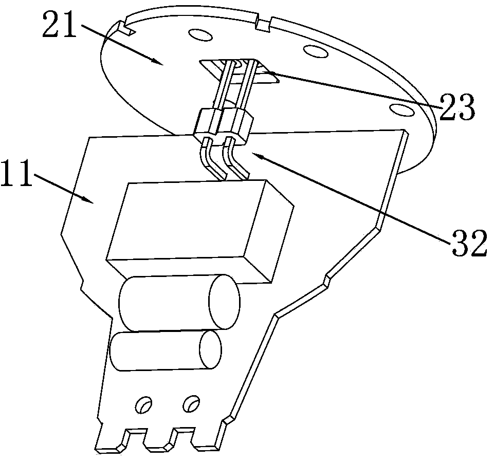
[0023] Embodiment 1: as Figure 1-3 As shown, the LED lamp of the present invention includes a power supply device 1 , an LED light source module 2 , a connection plate 31 and a connection pin 32 , and the LED light source module 2 includes a metal substrate 21 and an LED light source 22 disposed on the metal substrate 21 . The power supply device 1 of the present invention and the LED light source module 2 are connected through the connection plate 31 and the connection pin 32, and the specific connection method is as follows:

[0024] The metal substrate 21 is provided with a through hole 23, and the connection plate 31 is overlapped on the top of the through hole 23. The size of the connection plate 31 is larger than the size of the through hole 23. The connection plate 31 completely covers the through hole 23, and one end of the connection pin 32 penetrates through the hole 23. The connection plate 31 is welded and fixed through the through hole 23 , and the size of the th...

Embodiment 2

[0027] Embodiment 2: as Figure 4-6 As shown, the structure of embodiment 2 is similar to that of embodiment 1, and the structure of the connection plate 31 and the connection mode between the connection plate 31 and the metal substrate 21 are the same as those of embodiment 1, the difference is that the connection pin 32 consists of two The needles 36 in the shape of a straight bar are formed. The circuit board 11 includes a first circuit board 11a and a second circuit board 11b arranged perpendicular to each other, and the first circuit board 11a is arranged parallel to the metal substrate 21. The first circuit board 11a A third welding hole 13 is provided on it.

[0028] The specific connection method is: the connection plate 31 is arranged above the through hole 23 of the metal substrate 21 of the LED light source module 2, and one end of the connection pin 32 passes through the through hole 23 of the metal substrate 21 and the first welding hole 33 of the connection plate...


PUM


Abstract

The invention discloses an LED lamp and a circuit connecting method of the LED lamp. The LED lamp comprises a power supplying device and an LED light source module, the LED light source module comprises a metal substrate and an LED light source arranged on the metal substrate, the LED lamp further comprises a connecting board and a connecting pin, the connecting board is arranged on the metal substrate and is electrically connected with the metal substrate, one end of the connecting pin penetrates through the metal substrate and is welded to the connecting board, the other end of the connecting pin is fixedly connected with a power supplying device in a welding mode, and therefore the connecting pin is electrically connected with the power supplying device and the LED light source module. Compared with the prior art, according to the LED lamp and the circuit connecting method of the LED lamp, due to the fact that the connecting pin and the connecting board are connected with the power supplying device and the LED light source module and connecting welding points are arranged on the connecting board, false welding and cold joint caused by good heat dissipation performance of the metal substrate are avoided; in addition, the occurrence of short circuit due to the situation that conductive wires are broken caused by being scratched by the metal substrate can be avoided. The LED lamp is easy to weld and conductive wires to be welded are not needed to be fixed manually.

Description

technical field [0001] The invention relates to the technical field of LED lighting, in particular to an LED lamp and a circuit connection method for the LED lamp. Background technique [0002] Due to the advantages of energy saving, environmental protection, light control, solidification, and long life, LEDs have been widely used in various lighting fields today when low-carbon life is advocated. LED lights generally include components such as a power supply device, an LED light source module, and a bulb. The LED light source module includes a metal substrate and at least one LED light source disposed on the metal substrate. The power supply device generally includes a circuit board. [0003] In the prior art, wires are generally used to connect the power supply device and the metal substrate together by manual welding. However, manual welding is used, because the metal substrate dissipates heat well, and the welding time is not easy to control, and it is easy to false and ...

Claims


Application Information

Patent Timeline
Patent Type & Authority Applications(China)
IPC IPC(8): F21S2/00F21V23/06F21Y101/02
CPCF21K9/20F21V23/06F21Y2115/10H05K3/366
Inventor 金昌洲沈锦祥
Owner ZHEJIANG SHENGHUI LIGHTING
Why Eureka
Try Eureka