Small-sized energy-saving ventilator

A ventilator, a small-scale technology, applied in the field of heat exchange, can solve the problems of fan air volume reduction, resistance, and air volume that cannot meet the requirements of use, and achieve the effects of good balance and stability, flexible installation methods, and reduced volume

Active Publication Date: 2013-12-11
北京环都拓普空调有限公司
View PDF7 Cites 24 Cited by
  • Summary
  • Abstract
  • Description
  • Claims
  • Application Information

AI Technical Summary

Problems solved by technology

In the above design, the ventilation equipment is designed to be very thin, and the space between the air inlet of the fan and the box wall is very small, which will cause a very large resistance, resulting in a significant reduction in the air volume of the fan. Therefore, the actual air volume in use will be far less than 100CMH. In other words, in actual use, the above-mentioned thin models simply cannot meet the requirements of 33m 2 The ventilation requirements of the left and right single rooms
Because the actual residential area in China is much larger than 33m2 2 Therefore, the air volume generated by the ventilation system using the above-mentioned fans will be far from meeting the requirements of domestic houses. Therefore, the market versatility and transformability of the above-mentioned models have not been good.

Method used


Image

  • Small-sized energy-saving ventilator
  • Small-sized energy-saving ventilator
  • Small-sized energy-saving ventilator

Examples


no. 1 example

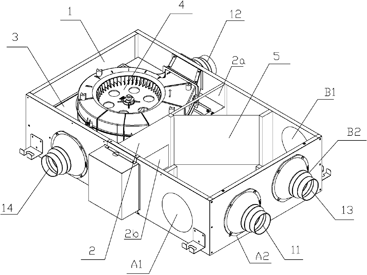
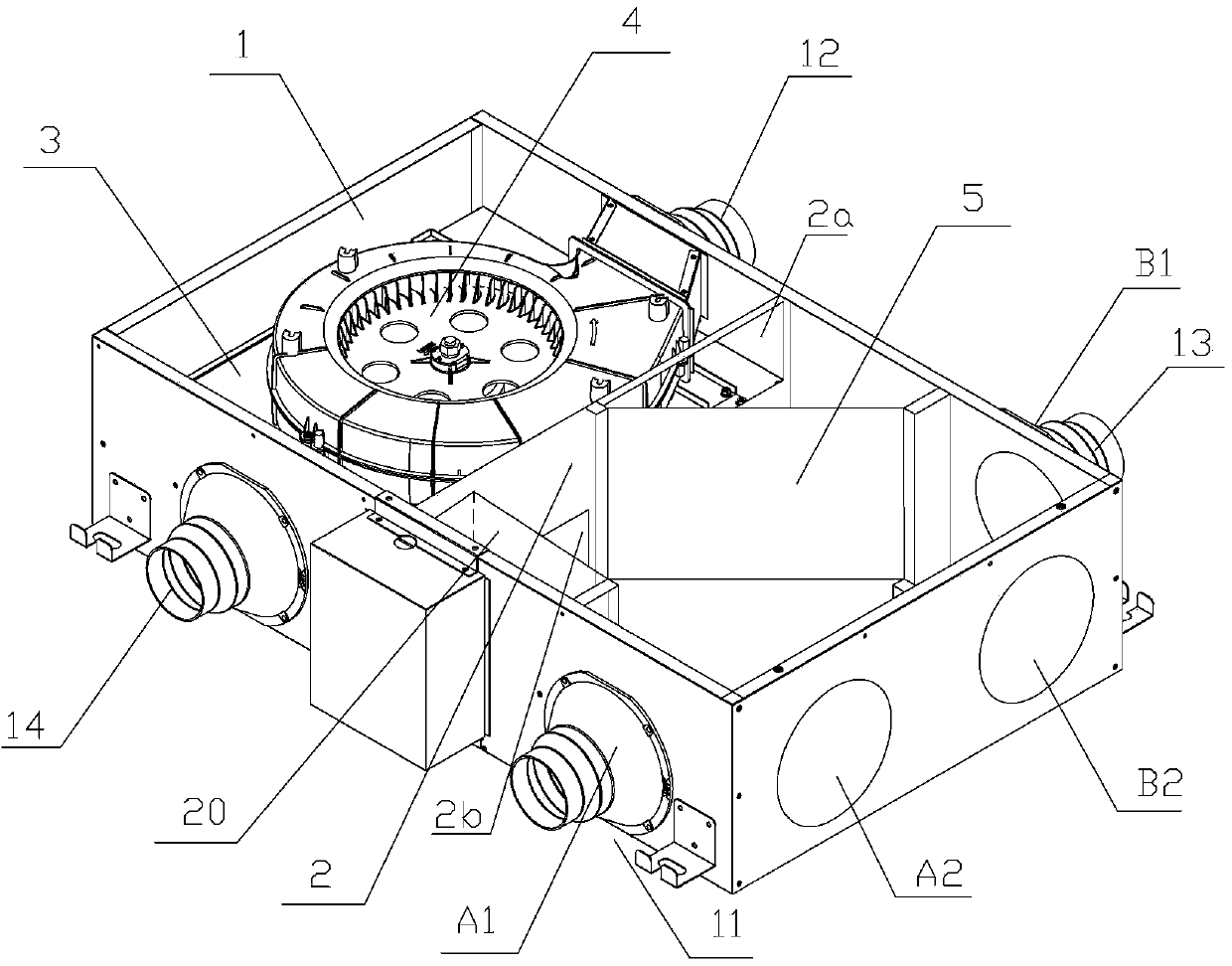
[0036] see figure 1 ,by figure 1 The orientation in the paper describes the structure of the small energy-saving ventilator. The small energy-saving ventilator has two rectangular bottom plates and top plates with equal areas ( figure 1not shown), and four side plates respectively used to connect the four sides of the bottom plate and the top plate, wherein the left side plate and the right side plate are the short side plates, and the front side plate and the rear side plate are the long side sides plate. The bottom plate, the top plate, the left side plate, the right side plate, the front side plate and the rear side plate form a flat rectangular casing 1 .

[0037] Inside the casing 1, a middle partition 2 parallel to the left side panel and an upper and lower partition 3 arranged on the left side of the middle partition 2 and perpendicular to the left side panel are arranged. The front and rear sides of the middle partition 2 are respectively connected with the front s...

no. 2 example

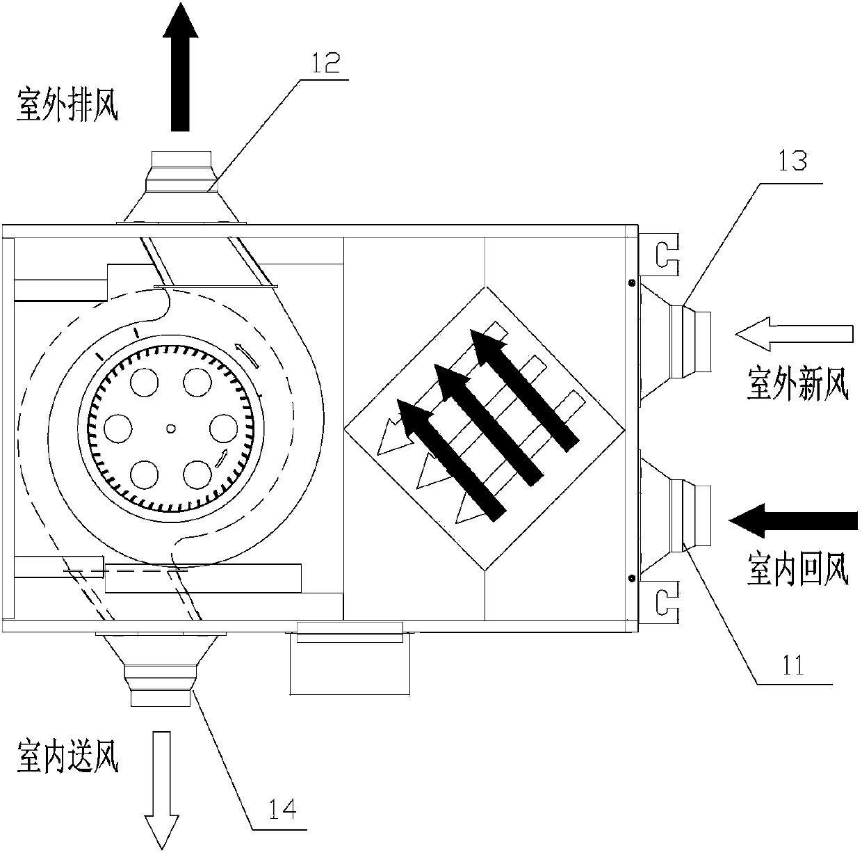
[0048] The second embodiment of the present invention is an improvement to the first embodiment, and the basic structure of the second embodiment is exactly the same as that of the first embodiment. The difference is that, in the second embodiment, by setting the second air return port 2a' and the second fresh air port 2b' on the intermediate partition 2, and by adding the fresh air baffle and the return air baffle, the fresh air channel and the A bypass channel is added outside the return air channel, so that the small energy-saving ventilator has a bypass ventilation function.

[0049] Such as Figure 5 As shown, the middle partition 2 has two fresh air outlets and two return air outlets. Among them, the middle partition 2 is bounded by the center line, and the upper part of the rear side is provided with a return air outlet 2a for connecting the upper outdoor air exhaust area and the right indoor return air area; Fresh air outlet 2b in the air supply area and the outdoor ...


PUM


Abstract

The invention provides a small-sized energy-saving ventilator which comprises a shell body composed of a top plate, a bottom plate, two long-edge side plates and two short-edge side plates. An intermediate partition plate for being connected with the top plate, the bottom plate and the two long-edge side plates is arranged inside the shell body, the intermediate partition plate is used for dividing the interior of a machine shell into two areas, one area is a heat exchanging area, and the other area is an exhausting area. A heat exchanger which is vertically placed is arranged in the heat exchanging area, two horizontally-rotating volute blowers are arranged in the exhausting area, and the two volute blowers are vertically stacked and are driven by the same double-shaft motor to rotate. In the small-sized energy-saving ventilator, the total stacked height of the two volute blowers is smaller than that of the heat exchanger, therefore, the whole height of the small-sized energy-saving ventilator depends on the height of the heat exchanger, therefore, under the premise that the ventilation requirement is ensured, the size of the small-sized energy-saving ventilator is reduced, and the small-sized energy-saving ventilator is suitable for being used in the house with the small installation space.

Description

technical field [0001] The invention relates to a small ventilation device, which belongs to the technical field of heat exchange. Background technique [0002] Along with the popularization and popularization of miniaturized houses, the demand for the use of small ventilation devices is increasingly strong. [0003] In the prior art, there are various designs of miniaturized ventilation devices. Among them, the thinnest ventilation device should be the ventilation device disclosed in the Chinese invention patent with the patent number ZL200510131429.5. The ventilation equipment includes: a fan device, a heat exchange unit and a casing, the casing has a first cavity and a second cavity, the heat exchange unit is placed in the first cavity, the fan device is placed in the second cavity, and the second cavity The cavity communicates with the first cavity. The casing of the ventilator has a thin and wide flat rectangular box shape, and the thickness of the casing is substant...

Claims


Application Information

Patent Timeline
Patent Type & Authority Applications(China)
IPC IPC(8): F24F7/08F24F13/30F24F13/00F24F12/00
Inventor 孟东辉
Owner 北京环都拓普空调有限公司
Why Eureka
Try Eureka