Inertial positioning method and system using vision-aided correction

An inertial positioning and visual technology, applied in the field of inertial positioning, can solve the problems of inconvenient strike experience, incorrect positioning and orientation information, etc., and achieve the effects of short correction time, accurate correction, and low power consumption

Active Publication Date: 2013-12-11
SHENZHEN HEZHI CHUANGYING ELECTRONICS
View PDF3 Cites 24 Cited by
  • Summary
  • Abstract
  • Description
  • Claims
  • Application Information

AI Technical Summary

Problems solved by technology

[0002] At present, the wide application of inertial sensors in space positioning has made us see obvious problems in the application. The biggest problem is that a point in 3D space has been calibrated and positioned. After moving this point The positioning and orientation information is not correct. If the user needs to obtain accurate positioning and pointing information, he must press the correction button again. When the user is constantly moving, it needs to be repeatedly manually corrected to get the pointing. Effect
The inconvenience caused by this problem seriously hits the user experience!

Method used


Image

  • Inertial positioning method and system using vision-aided correction
  • Inertial positioning method and system using vision-aided correction
  • Inertial positioning method and system using vision-aided correction

Examples


Embodiment Construction

[0062] In order to have a clearer understanding of the technical features, objectives and effects of the present invention, the specific embodiments of the present invention will now be described in detail with reference to the accompanying drawings.

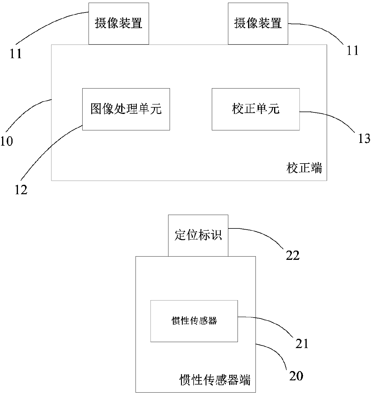
[0063] The inertial positioning method and system using vision-assisted correction of the present invention provide separate camera modules and positioning marks; wherein, the camera module is set at the calibration end and the positioning mark is set at the inertial sensor end, or the positioning mark is set at the correction end, And the camera module is set on the inertial sensor end. Then, use the camera module to photograph the positioning marks, and calculate the correction data according to the photographing results; use the correction data to correct the sensing data of the inertial sensor, which can realize the detection of the inertial sensor in the inertial positioning device with little power consumption. Error correcti...


PUM


Abstract

The invention discloses an inertial positioning method and an inertial positioning system using vision-aided corrosion. The inertial positioning system comprises an inertial sensor, a positioning identifier, an image pickup module, an image processing unit and a correcting unit, wherein the positioning identifier is used for identifying a positioning point; the image pickup module is used for obtaining image information of the positioning identifier. The image processing unit is used for calculating space position information according to the image information generated by the image pickup module and transmitting the space position information to the correcting unit; the correcting unit is used for carrying out correction on sensed data of the inertial sensor according to the space position information. The inertial positioning method comprises the steps of arranging the image pickup module and the positioning identifier which are separate, wherein the image pickup module is arranged at the correcting end and the positioning identifier is arranged at the inertial sensor end; or the positioning identifier is arranged at the correcting end and the image pickup module is arranged at the inertial sensor end; picking up the positioning identifier by utilizing the image pickup module, and calculating according to the pickup result to obtain the correction data; correcting the sensed data of the inertial sensor by utilizing the correction data. The inertial positioning method has the advantages of being short in correction time, accurate in correction, less in power consumption and the like.

Description

Technical field [0001] The present invention relates to an inertial positioning method and system, and in particular to an inertial positioning method and system using visual assisted correction. Background technique [0002] At present, inertial sensors are widely used in spatial positioning, so that we have also seen obvious problems in applications. The biggest problem is that a point in the three-dimensional space has been calibrated and positioned. After moving this point The positioning and orientation information is incorrect. If the user needs to obtain accurate positioning and pointing information, he must press the correction button again. When the user is constantly moving, it needs to be repeatedly artificially corrected to get the point. effect. The inconvenience caused by this problem has severely affected the user experience! Summary of the invention [0003] The technical problem to be solved by the present invention is to provide an inertial positioning method a...

Claims


Application Information

Patent Timeline
Patent Type & Authority Applications(China)
IPC IPC(8): G01C25/00G01C21/16
Inventor 罗富强纪家纬
Owner SHENZHEN HEZHI CHUANGYING ELECTRONICS
Why Eureka
Try Eureka