Joint calibration method of vision and satellite positioning sensor for robot navigation

A visual sensor, satellite positioning technology, applied in the field of integrated navigation

Inactive Publication Date: 2016-06-01
SHANGHAI MARITIME UNIVERSITY
View PDF0 Cites 0 Cited by
  • Summary
  • Abstract
  • Description
  • Claims
  • Application Information

AI Technical Summary

Problems solved by technology

[0005] The present invention aims to solve the problem of joint calibration of vision sensors and satellite positioning sensors, and provides a joint calibration method of vision and satellite positioning sensors suitable for robot navigation, which can calculate the longitude, latitude and altitude based on the output of satellite positioning sensors at any time. Get the longitude, latitude and altitude of the vision sensor center

Method used


Image

  • Joint calibration method of vision and satellite positioning sensor for robot navigation
  • Joint calibration method of vision and satellite positioning sensor for robot navigation
  • Joint calibration method of vision and satellite positioning sensor for robot navigation

Examples


Embodiment Construction

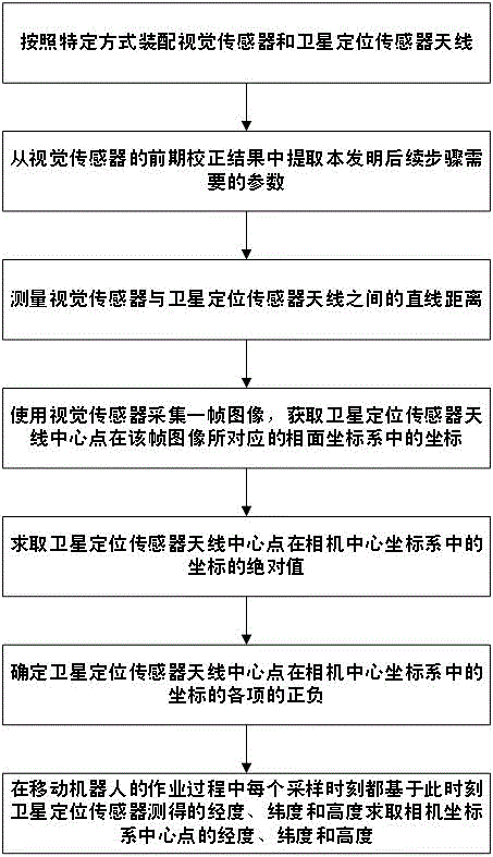
[0023] In order to better explain the problem, first declare the coordinate system involved in the present invention here:

[0024] The earth-centered earth-fixed coordinate system (represented by e in the present invention) is a right-handed coordinate system. The center of the earth is the origin, the x-axis points to the prime meridian, the y-axis points to 90 degrees east longitude, and the z-axis coincides with the earth's rotation axis and points to the North Pole. According to different expressions, the coordinates under e have two equivalent expressions: Cartesian coordinates, using (x e ,y e ,z e ) represents; geodetic coordinates, with longitude λ, latitude Height h said.

[0025] The local geographic coordinate system (represented by g in the present invention) is a right-handed coordinate system. The origin of the coordinate system is arbitrary, so whenever the local geographic coordinate system is expressed in the subsequent discussions of the present invent...


PUM


Abstract

The invention provides a vision and satellite positioning sensor joint calibrating method suitable for robot navigation. The vision and satellite positioning sensor joint calibrating method comprises the steps of: ensuring that each frame of image of a center point of a satellite positioning sensor antenna in a vision sensor is visible during assembly; acquiring a front-stage correction result of the vision sensor, a straight line distance between the vision sensor and the satellite positioning sensor antenna, and coordinates of the center point of the satellite positioning sensor antenna in an image surface coordinate system of a certain frame of image, solving absolute values of the coordinates of the center point of the satellite positioning sensor antenna in a camera center coordinate system and plus and minus of all items; determining coordinates of an original point of the camera center coordinate system in an equivalent coordinate system; and solving a longitude, a latitude and a height of the original point of the camera center coordinate system based on a longitude, a latitude and a height measured by a satellite positioning sensor at every sampling moment so that errors caused by assembling centers of the satellite positioning sensor and the vision sensor in different space points are jointly calibrated.

Description

technical field [0001] The invention is applicable to the field of combined navigation of robot navigation and ordinary carriers, and in particular relates to a combined calibration method of vision and satellite positioning sensors suitable for robot navigation. Background technique [0002] For example, in the field of robot navigation and combined navigation of ordinary carriers, in order to improve the accuracy of navigation and adaptability in various environments, various sensors are often assembled on the carrier, but these sensors are often not assembled at the same point in space. That is to say, the fields of view of various sensors are different. Therefore, if it is directly assumed that the observations between different sensors originate from the same datum for coordinate projection, it will cause a global error in the final result. Therefore, how to calibrate various sensors is a necessary technical link. The most common problem is how to calibrate the misalig...

Claims


Application Information

Patent Timeline
Patent Type & Authority Patents(China)
IPC IPC(8): G01C25/00G01S19/23
Inventor 孙作雷张波黄平平曾连荪朱大奇
Owner SHANGHAI MARITIME UNIVERSITY
Why Eureka
Try Eureka