Real-time pose determination method, device and electronic equipment

A technology for determining the method and pose, applied in the image field, can solve problems such as map data drift and inaccurate pose information, and achieve the effect of improving accuracy and calibrating errors

Active Publication Date: 2021-04-06
GUANGZHOU XAIRCRAFT TECH CO LTD
View PDF6 Cites 0 Cited by
  • Summary
  • Abstract
  • Description
  • Claims
  • Application Information

AI Technical Summary

Problems solved by technology

However, the map created based on the collected images has the problem of data drift. At the same time, the location information of the created map using monocular vision SLAM is relative coordinates rather than absolute coordinates in the real space, which leads to The pose information determined by the map is not accurate enough

Method used


Image

  • Real-time pose determination method, device and electronic equipment
  • Real-time pose determination method, device and electronic equipment
  • Real-time pose determination method, device and electronic equipment

Examples


no. 1 example

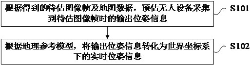
[0059] Please refer to figure 2 , figure 2 A real-time pose determination method provided by an embodiment of the present invention is shown. Such as figure 2 As shown, the above-mentioned real-time pose determination method may include the following steps:

[0060] Step S101, according to the obtained image frame to be estimated and the map data, estimate the output pose information when the unmanned device collects the image frame to be estimated.

[0061] The above-mentioned image frames to be estimated are images for evaluating the pose of the unmanned device. Each image frame to be estimated corresponds to a piece of positioning data. The image frame to be estimated and the corresponding positioning data have the same acquisition time point.

[0062] In some embodiments, the image frame to be estimated is an image frame generated after processing the image data collected by the unmanned device. In other words, the image frame to be estimated is an image frame indi...


PUM


Abstract

Embodiments of the present invention provide a real-time pose determination method, device and electronic equipment, which relate to the field of image technology. Wherein, the above real-time pose determination method estimates the output pose information when the unmanned device collects the image frame to be estimated according to the obtained image frame to be estimated and the map data; wherein, the map data is based on the acquisition time A map created by the historical image frame earlier than the image frame to be estimated and the positioning data of the historical image frame; according to the geographic reference model, converting the output pose information into real-time pose information in the world coordinate system; Wherein, the geographic reference model is a model used for data conversion between the visual coordinate system and the world coordinate system. Thereby improving the error caused by map drift and improving the accuracy of the obtained pose information.

Description

technical field [0001] The present invention relates to the field of image technology, in particular to a real-time pose determination method, device and electronic equipment. Background technique [0002] The emergence of simultaneous localization and mapping (SLAM) technology enables unmanned equipment (drones, robots, etc.) to achieve autonomous navigation in unknown environments, and further promotes the development of unmanned equipment. [0003] At present, monocular vision SLAM is widely used. It tracks each frame of image collected and then creates a map to facilitate pose determination. However, the map created based on the collected images has the problem of data drift. At the same time, the location information of the created map using monocular vision SLAM is relative coordinates rather than absolute coordinates in real space, which leads to The pose information determined by this map is not accurate enough. Contents of the invention [0004] In view of this,...

Claims


Application Information

Patent Timeline
Patent Type & Authority Patents(China)
IPC IPC(8): G01C21/00
CPCG01C21/005
Inventor 杨坤
Owner GUANGZHOU XAIRCRAFT TECH CO LTD
Why Eureka
Try Eureka