
Testing device for shear-resistant fatigue property of chemical anchoring stud

A fatigue test and fatigue performance technology, applied in the field of shear fatigue performance test equipment, can solve the problems of incomplete collection of mechanical performance parameters, poor fixture versatility and reusability, and affect the shear force of studs, so as to ensure pure Shear stress state, improved recycling efficiency, and wide application range

Inactive Publication Date: 2015-07-15
CENT SOUTH UNIV +1
View PDF4 Cites 0 Cited by
  • Summary
  • Abstract
  • Description
  • Claims
  • Application Information

AI Technical Summary

Problems solved by technology

At present, there are still many problems in the shear fatigue performance test of chemical anchor bolts: (1) After a long time of use, the fixture itself is prone to loosening or position deviation, resulting in the failure of the shear force to act vertically on the test object. Affect the reliability of the test results; (2) After the stud is subjected to the shear force, the contact surfaces of the two fixtures contact and generate friction, which interferes with the shear force acting on the stud and affects the test results; (3) Due to the fluidity of the chemical anchoring glue, it often occurs that the chemical anchoring glue overflows and bonds the fixture together, which seriously affects the shear force of the stud; (4) The existing fixture has poor versatility and reusability , often after a test is completed, the fixture is invalid because the consolidated chemical anchoring glue cannot be removed, and the specific fixture can only be used for a specific fatigue testing machine, and the field of use is narrow; (5) the existing fixture cannot be used in After the shear fatigue test of the chemical anchor studs is completed, the pullout ultimate bearing capacity test after the stud fatigue is further carried out, resulting in incomplete collection of mechanical performance parameters

Method used


Image

  • Testing device for shear-resistant fatigue property of chemical anchoring stud
  • Testing device for shear-resistant fatigue property of chemical anchoring stud
  • Testing device for shear-resistant fatigue property of chemical anchoring stud

Examples


Embodiment Construction

[0042] It should be understood that the specific embodiments described here are only used to explain the present invention, not to limit the present invention.

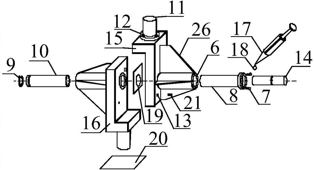
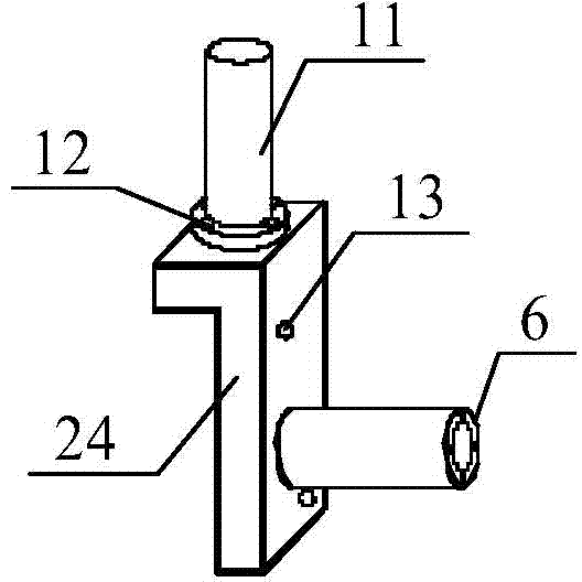
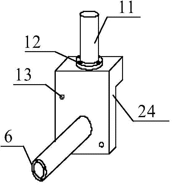
[0043] figure 1 It is a schematic diagram of the exploded structure of the chemical anchor stud anti-shear fatigue performance test device of the embodiment of the present invention; Figure 2-a , Figure 2-b is the axonometric view of the first fixture and the second fixture without sleeve stiffeners; Figure 2-c , Figure 2-d is the axonometric view of the first fixture and the second fixture with sleeve stiffeners; Figure 3-a , Figure 3-b , Figure 3-c is a schematic diagram of the assembly of the first fixture and the second fixture; Figure 4 is the axonometric drawing of the sleeve with circlip; Figure 5-a , Figure 5-b is the axonometric drawing of the T-sleeve; Figure 6-a , Figure 6-b , Figure 6-c , Figure 6-d , Figure 6-e , Figure 6-f , Figure 6-g , Figure 6-h , Figure 6-i It is a...


PUM


Abstract

The invention provides a testing device for a shear-resistant fatigue property of a chemical anchoring stud. The testing device comprises a fatigue tester transverse beam (2) and a fatigue tester pedestal (3), wherein the fatigue tester transverse beam (2) is connected with the fatigue tester pedestal (3) by fatigue tester uprights (1), and a fixture assembly guaranteeing a pure shear stress state of the stud during a fatigue test is arranged between the fatigue tester transverse beam (2) and the fatigue tester pedestal (3). The testing device is reasonable in design, simple in structure and easy to operate and use; a T-shaped flange is arranged, and connected by a bolt, so that the testing device can be matched with testers in multiple specifications for use; and an application scope of the testing device is wider.

Description

technical field [0001] The invention relates to the technical field of a shear fatigue performance test device, in particular to a chemical anchor stud shear fatigue performance test device. Background technique [0002] At present, chemical anchoring studs are widely used in civil engineering to strengthen and strengthen in-service bridge structures, especially in the anchoring of ballastless track slabs in high-speed railways. In order to ensure effective anchorage between the ballastless track slab and the bridge deck under the dynamic load of the train, it is usually used to drill holes in the ballastless track slab and the bridge deck, then fill the holes with chemical anchoring glue, and insert bolts to anchor the two together. Under the dynamic load of the train, once the shear failure of the studs occurs, it will directly affect the stability of the high-speed railway track slab, thereby affecting the safety of the high-speed railway line operation. Therefore, the s...

Claims


Application Information

Patent Timeline
Patent Type & Authority Patents(China)
IPC IPC(8): G01N3/04G01N3/32
Inventor 朱志辉
Owner CENT SOUTH UNIV
Learn More