An implant

An implant and prosthesis technology, applied in the field of orthopedic surgery, can solve the problems of inflexible position and loss of joint mobility.

Active Publication Date: 2013-12-11
DEPUY (IRELAND) LTD
View PDF9 Cites 2 Cited by
  • Summary
  • Abstract
  • Description
  • Claims
  • Application Information

AI Technical Summary

Problems solved by technology

[0006] Some known prostheses suffer from inflexibility in the location of the attachment points used to couple the bone fragments and soft tissue to the implant, which can lead to loss of mobility in the repaired joint

Method used


Image

  • An implant
  • An implant
  • An implant

Examples


no. 1 example ,120124 and 128。 pic 7124 and 128, pic 8 1 。 pic 3 to 22 no. 2 example 120

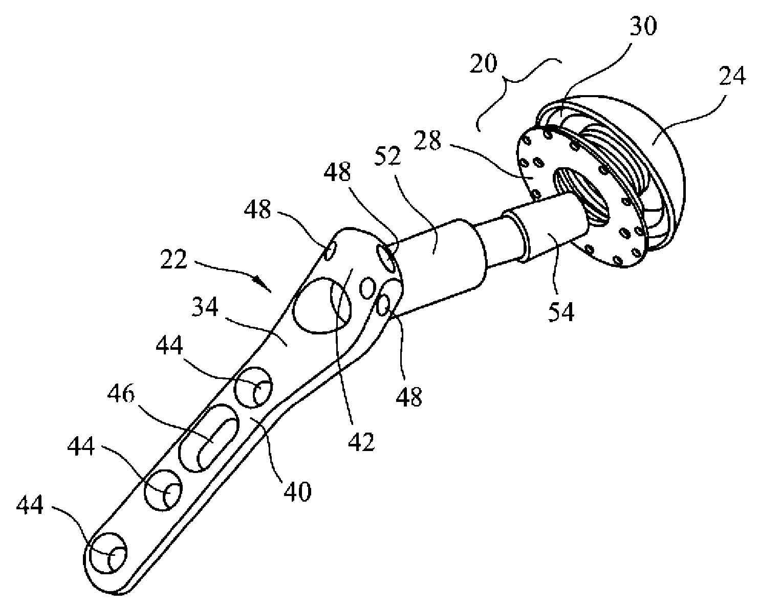
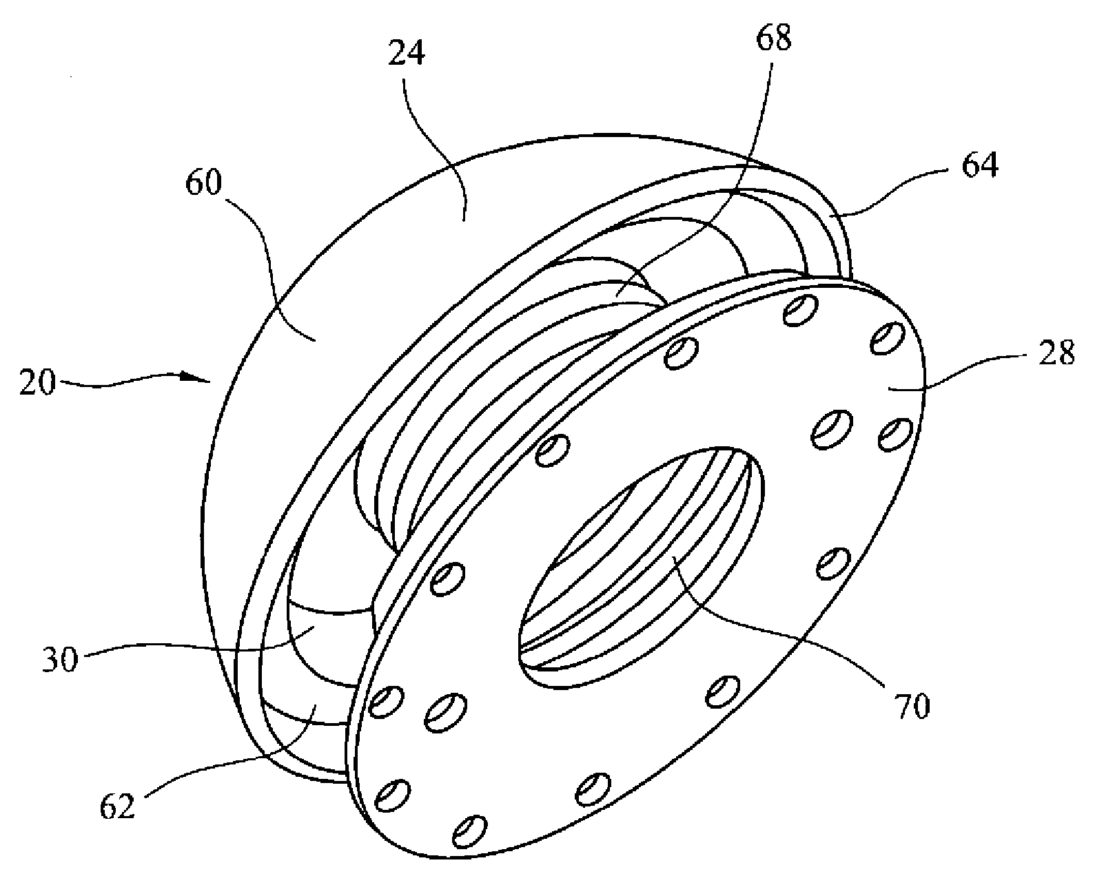
[0062] Articulation member 124 includes a convex load-bearing surface 160 , and an opposing surface 162 that includes depression 130 . The convex bearing surface 160 may be defined by a portion of a sphere. The opposite surface 162 is substantially occupied by the recess 130 , which is shown extending across nearly the entire width of the opposite surface 162 within the rim 164 . The recess 130 extends around a receptacle 166 which is tapered and arranged to form a tapered lock to the taper 54 at the end of the neck portion 26 of the arthroplasty plate 22 .

[0063] The depression 130 forms an annular ring around the receptacle 166 . The outer edge of the receptacle 166 is provided with an annular rib 180 . Collar 128 includes a bore 182 defined by a raised rim 184 corresponding to the outer shape of receptacle 166 , and includes an annular groove 186 . The rim 184 is resiliently deformable such that when pressed onto the receptacle 166 the rim 184 expands to allow the groo...


PUM


Abstract

An implant (20), prosthesis and method of use are described. The implant comprises an articulation component (24) having a bearing surface (60) and a reverse surface (62) arranged to couple to a proximal neck portion (26) of an arthroplasty implant (22) coupled to a bone. A collar (28) is arranged to couple to the reverse surface of the articulation component. The collar defines a neck hole (70) arranged to pass around the coupling between the articulation component and the proximal neck portion of the arthroplasty implant. The collar and the articulation component comprise complementary coupling features to secure the collar to the articulation component. The collar further comprises a plurality of attachment portions (74) to couple the collar to bone fragments or soft tissues. The prosthesis comprises the implant and an arthroplasty implant having a distal portion arranged to be coupled to an end of a long bone and a proximal neck portion.

Description

technical field [0001] The present invention relates generally to orthopedic surgery, and in particular, to shoulder prostheses. More particularly, the invention relates to implants forming part of a humeral prosthesis. In particular, the implant includes an articulation member for articulation against the glenoid implant or natural glenoid cavity. The invention also relates to assembled prostheses, and shoulder arthroplasty procedures using humeral prostheses. Background technique [0002] The natural shoulder joint can undergo degenerative changes, such as arthritis, for a variety of reasons. Alternatively, the shoulder joint may be fractured, or otherwise damaged by external forces. When the shoulder joint is sufficiently degenerated or damaged, it may be necessary to replace the natural shoulder joint with a prosthetic shoulder joint. Traditional shoulder prostheses include a humeral implant optionally with a glenoid implant. [0003] Typically, humeral implants inc...

Claims


Application Information

Patent Timeline
Patent Type & Authority Applications(China)
IPC IPC(8): A61F2/30A61F2/40
CPCA61B17/842A61F2/30728A61F2/4059A61F2/4637A61F2002/30332A61F2002/30367A61F2002/30461A61F2002/30538A61F2002/30729A61B17/746A61B17/06166A61B17/68A61F2/4014A61F2002/30245A61F2/4684A61F2002/30433A61F2002/3055
Inventor A.埃克伦S.戈捷
Owner DEPUY (IRELAND) LTD
Why Eureka
Try Eureka