Fluid-actuated diaphragm drive

A driver and diaphragm technology, applied in the direction of fluid pressure actuation devices, etc., can solve problems such as difficult to clean and easy to be polluted, and achieve an effect that is conducive to effective cleaning

Inactive Publication Date: 2013-12-11
FESTO AG & CO KG
View PDF6 Cites 8 Cited by
  • Summary
  • Abstract
  • Description
  • Claims
  • Application Information

AI Technical Summary

Problems solved by technology

However, due to the interlocking structures, there is a strongly cracked outer surface of the housing, which is very susceptible to contamination and difficult to clean
The risk of damage at the rather exposed edges of the bayonet connection must also not be underestimated

Method used


Image

  • Fluid-actuated diaphragm drive
  • Fluid-actuated diaphragm drive
  • Fluid-actuated diaphragm drive

Examples


Embodiment Construction

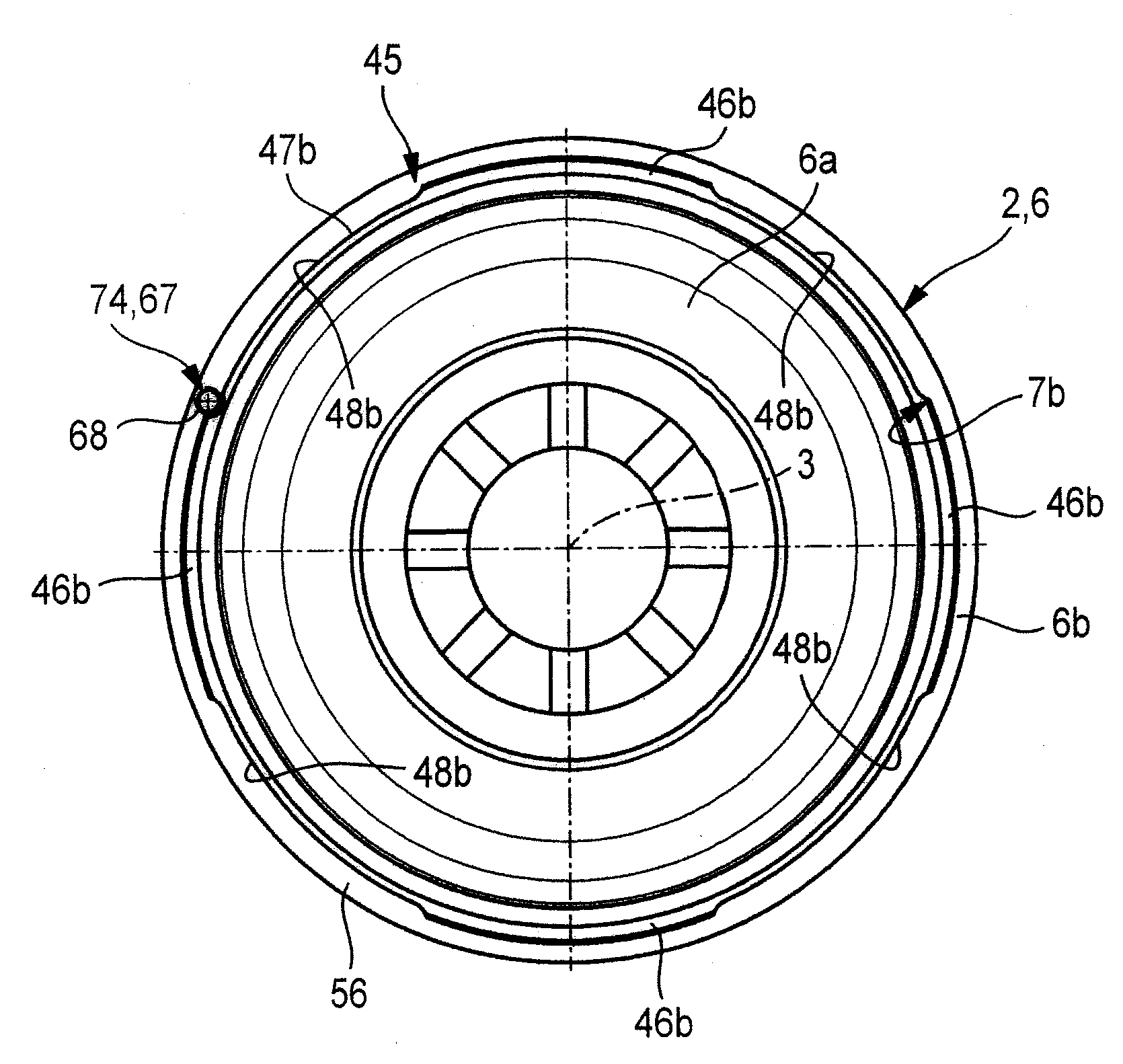
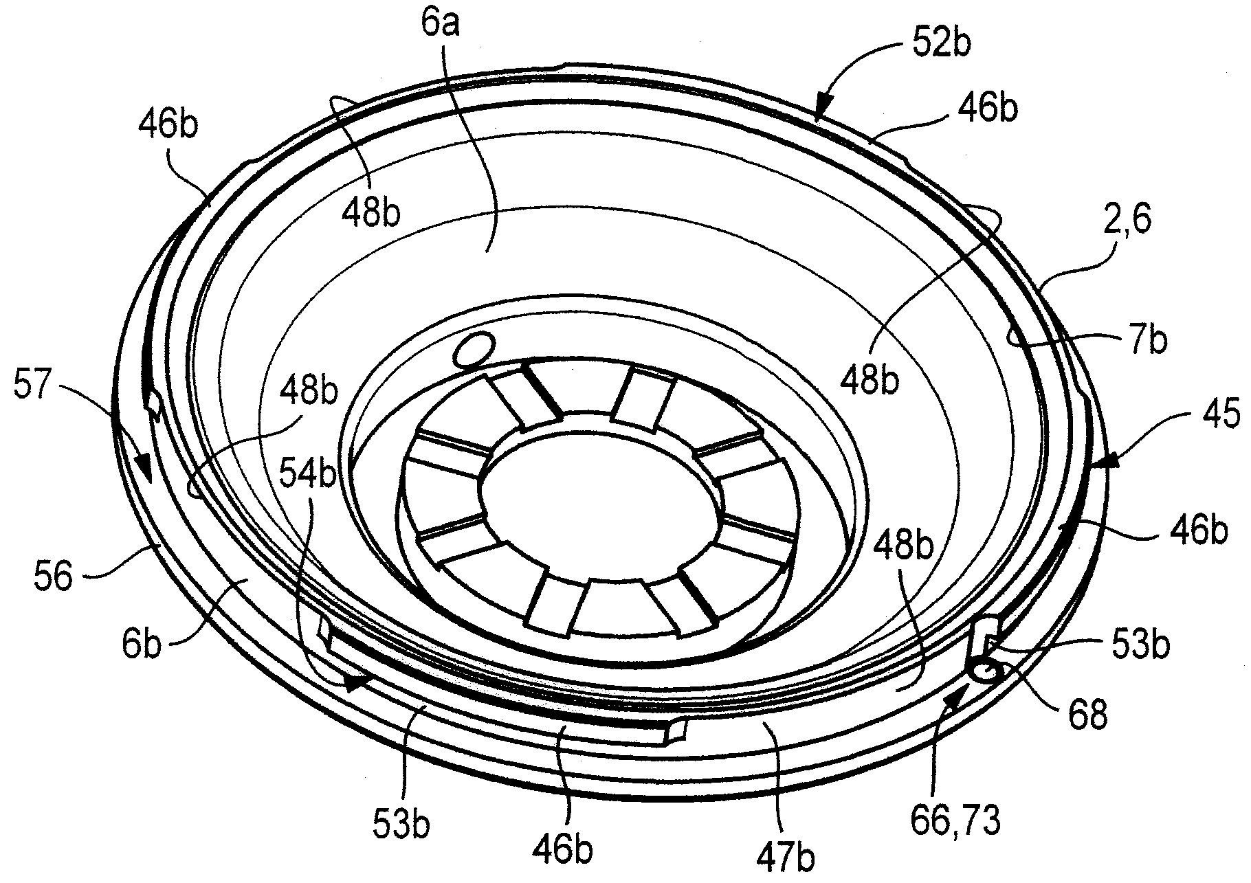
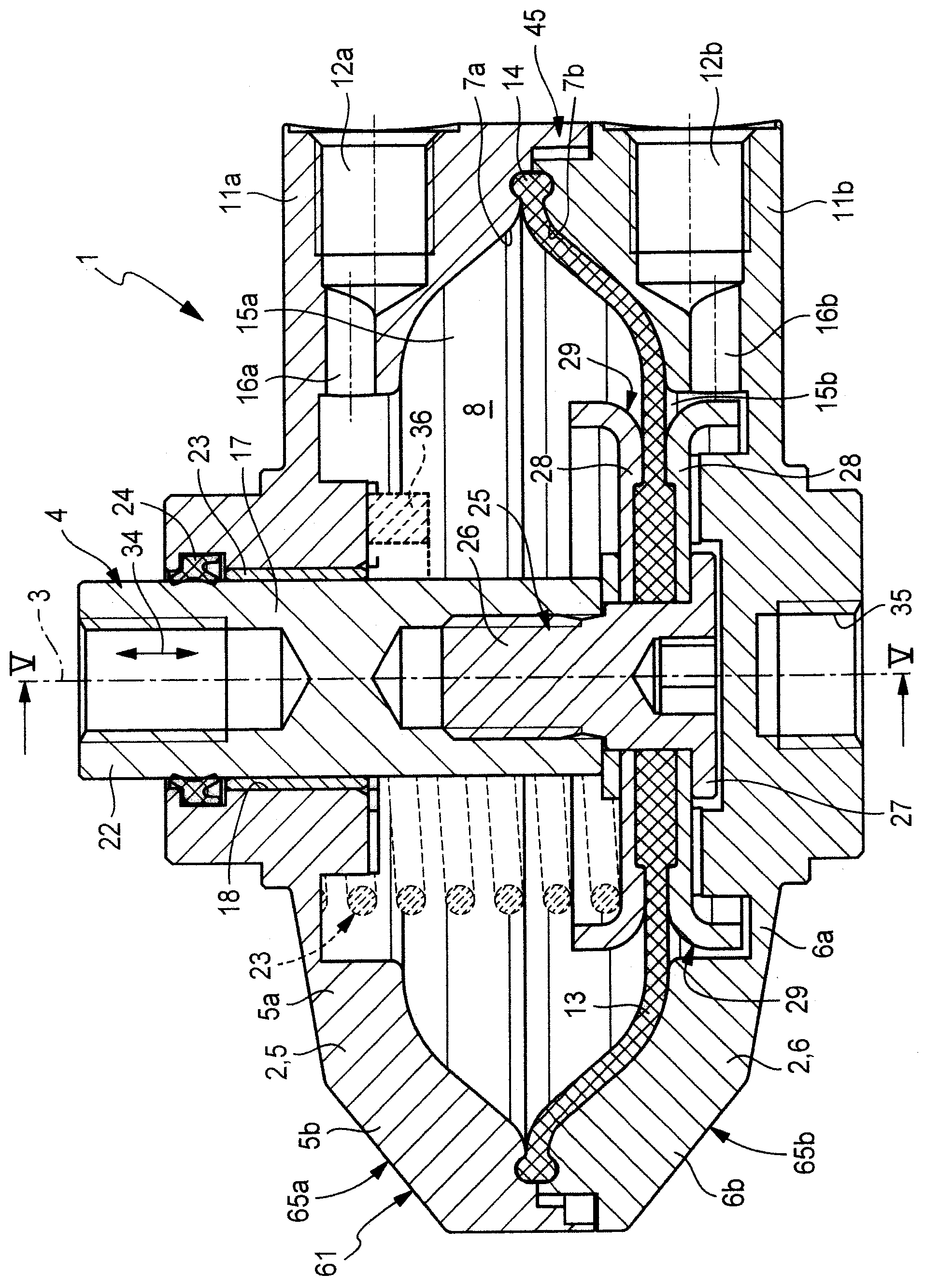
[0062] The diaphragm drive, which is denoted as a whole by the reference number 1 , is designed for controlled actuation by means of fluid forces, wherein the fluid forces are provided by a fluid drive medium which can be fed in and out as required. The drive medium is especially compressed air. However, the diaphragm drive can also be operated with other gaseous drive media and also with liquid drive media.

[0063] The diaphragm drive 1 has a housing 2 with a longitudinal axis 3 . It also has a drive unit 4 that is linearly movable relative to the housing 2 in the axial direction of the longitudinal axis 3 . The relative movement of the drive unit 4 with respect to the housing 2 is brought about by a controlled fluid loading on the drive medium.

[0064] The housing 2 has two bell-shaped housing parts 5 , 6 , which are subsequently also referred to as first and second housing parts 5 , 6 for better differentiation. Each housing part 5 , 6 has an in particular approximatel...


PUM


Abstract

Proposed is a fluid-actuated diaphragm drive (1) which has two dome-shaped housing parts (5, 6) which are mounted on one another with two openings, which face towards one another, arranged coaxially. The two housing parts (5, 6) are fixed to one another, at their side surfaces (5b, 6b) which adjoin one another, by means of a bayonet connection device (45). The two housing parts (5, 6) are designed such that the locking projections (46a, 46b) of the bayonet connection device (45) are covered so as not to be visible from the outside.

Description

technical field [0001] The invention relates to a fluid-actuated diaphragm drive with a housing having a longitudinal axis, the housing having two end faces each formed at a distance from each other in the axial direction of the longitudinal axis. Two cap-shaped housing parts of one of the end walls, which each have an opening surrounded by an annular side wall and which are placed coaxially within the common delimitation of the housing interior and the openings facing each other are fixed to each other and in the region of the annular side walls by a bayonet connection formed by a rearward locking projection (Verriegelungsvorsprung) of the housing parts; An axially deflectable diaphragm between the body parts, the diaphragm is drivingly connected to a rod body slidably passing through at least one of the end walls and fluid-tightly divides the housing cavity into two axially adjacent working chambers, at least one of which is fluid loadable. Background technique [0002] ...

Claims


Application Information

Patent Timeline
Patent Type & Authority Applications(China)
IPC IPC(8): F15B15/10
CPCF15B15/10
Inventor K.施托尔U.克斯H.勒里希
Owner FESTO AG & CO KG
Why Eureka
Try Eureka