Knitting machine

A knitting machine and knitting needle technology, applied in the field of knitting machines, can solve problems such as increasing production costs, and achieve the effects of reducing production costs, reducing manufacturing precision, and fast and easy assembly and replacement.

Inactive Publication Date: 2004-03-17
AMTEC CO LTD
View PDF9 Cites 3 Cited by
  • Summary
  • Abstract
  • Description
  • Claims
  • Application Information

AI Technical Summary

Problems solved by technology

The disadvantage of this configuration lies in the high demands on the precision, parallelism and length of the sliding support for the needle cam sector, which is in the direction perpendicular to the base plate of the needle cam sector. Indispensable in preventing it from getting stuck during exercise
Another disadvantage of the free seating of the needle cam sector on the needle cam carriage without fastening mechanisms is the risk that, during its careful assembly, the needle cam sector could be damaged if dropped. Make the needle cam fan-shaped plate drop out of the sliding yarn guide
In some positions of the needle carriage the possible protection against the needle cam sector falling out by increasing the length of the sliding thread guide becomes ineffective, and according to known types of connectors The principle is to lock the fan-shaped plate of the knitting needle triangle seat through the spring, which will increase the production cost

Method used


Image

  • Knitting machine
  • Knitting machine
  • Knitting machine

Examples


Embodiment Construction

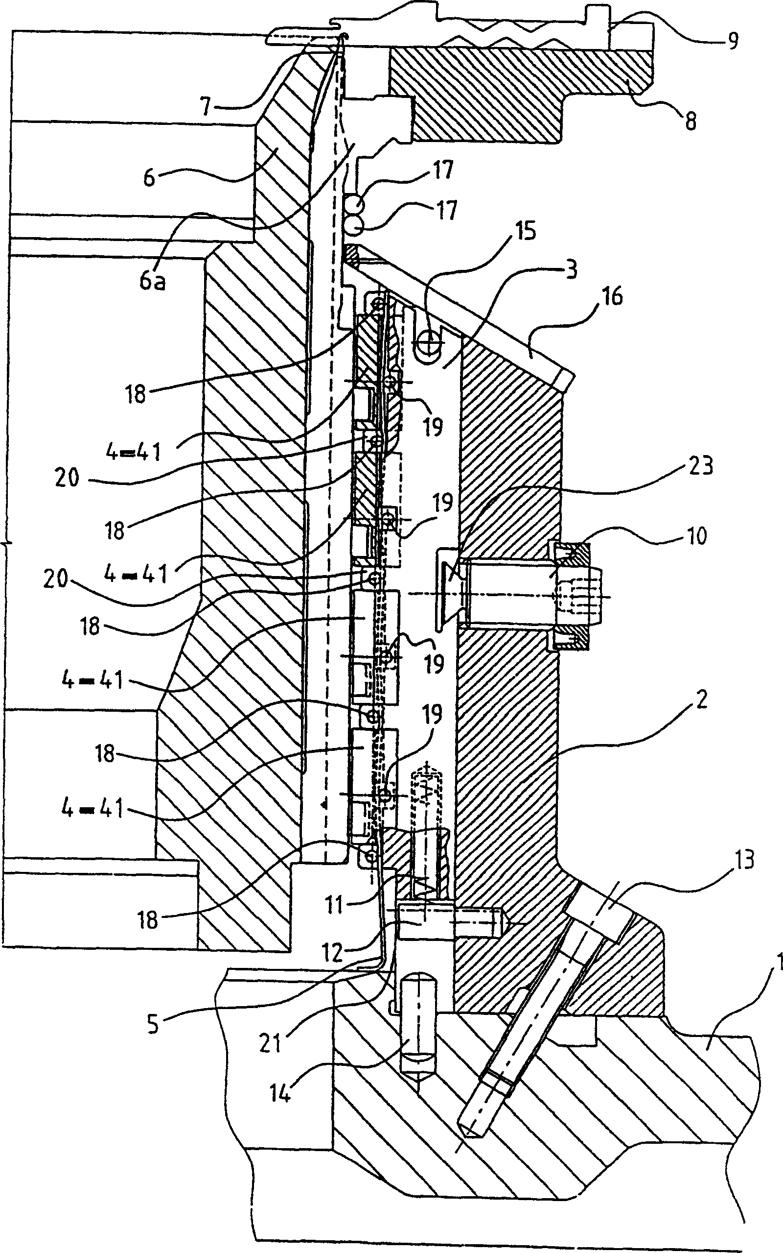
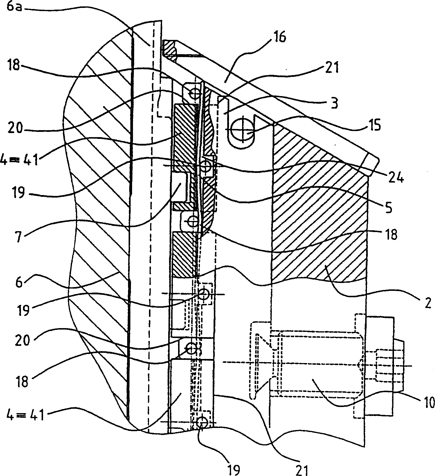
[0035] The present invention will be illustrated with a circular knitting machine with a single base plate, the parts that are more important to the present invention are shown in section in figure 1 , and in the area of ​​a circular cylindrical base plate 6 is shown as a knitting needle cam seat system, and shows the details necessary to illustrate the principles of the invention. Details about the fixing and driving of the base plate 6 and sinker seat 8, as well as the common configuration of the needle cams for controlling the knitting mechanism - the needles 7 and the sinker 9 - are well known to those skilled in the art, and Therefore, illustration thereof has been omitted for simplification of description.

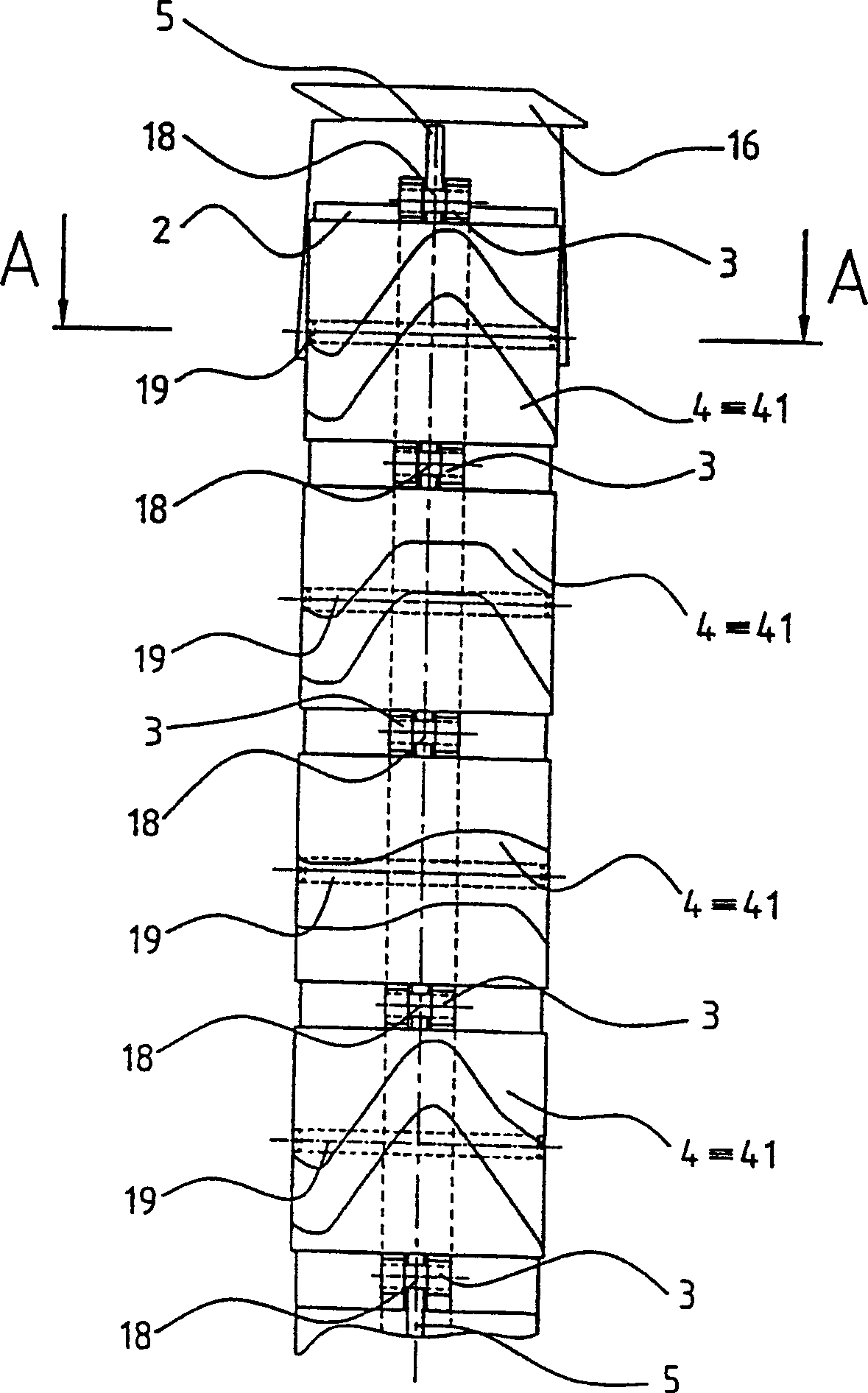
[0036] This knitting machine carries a knitting needle cam seat fan-shaped plate carriage 1, and at least one fixed part 2 of this knitting needle cam seat carriage is fixed on the carriage 1 with screws 13, wherein the rib with the bottom plate 6 The movable part 3...


PUM


Abstract

The invention relates to a knitting machine with at least one bed with ribs between which knitting means are situated free to move and coupled with needle cams serving to control them, each of them consisting of at least one needle cam section (4), with needle cams arranged on at least one needle cam carrier arranged at a fixed distance from the bed on at least one carrier (1) of needle cam blocks and fitted with attachment and positioning means for fixing the needle cam sections (4) and for keeping the position of the needle cam sections in relation to the stationary and/or movable part (2, 3) of the needle cam carrier, said attachment and positioning means permitting in the dismantled state of the needle cam carrier to mount and/or to remove the needle cam sections (4) from the front side of the needle cam carrier. The attachment means consists of at least one shifting attachment means (5) arranged substantially parallel to the front side (21) of the needle cam carrier by means of which at least one needle cam section (4) is held on the needle cam carrier and of at least one positioning means arranged substantially normal to the front side (21) of the needle cam carrier by means of which the needle cam sections (4) are held in required position in relation to the needle cam carrier.

Description

technical field [0001] The invention relates to a knitting machine having at least one base plate with ribbed beams between which the knitting mechanism is positioned free to move and associated with a needle cam for controlling them Connecting, each knitting mechanism comprises at least one knitting needle cam fan-shaped plate, so that the knitting needle cam is arranged on at least one knitting needle cam carriage, and the carriage is arranged on at least one carriage of the knitting needle cam slider set at a fixed distance away from the bottom plate, and assembled with a fastening and positioning mechanism, to fix the needle cam fan-shaped plate and to keep the needle cam fan-shaped plate relative to the needle cam carriage. The position of the moving and / or movable part, the fastening and positioning mechanism allows the installation and / or removal of the needle cam sector from the front of the needle cam carriage in the disassembled state of the needle cam carriage plat...

Claims


Application Information

Patent Timeline
Patent Type & Authority Applications(China)
IPC IPC(8): D04B15/32
CPCD04B15/32
Inventor 费朗齐歇克·布什库拉
Owner AMTEC CO LTD
Why Eureka
Try Eureka