Check patentability & draft patents in minutes with Patsnap Eureka AI!

Automotive fluidic pump

A fluid pump, vehicle technology, applied in the direction of fluid clutches, clutches, mechanical equipment, etc., can solve the problems of inability to fail protection, inability to engage or connect couplings, incompatibility, etc.

Inactive Publication Date: 2013-12-11
PIERBURG PUMP TECH
View PDF7 Cites 2 Cited by
  • Summary
  • Abstract
  • Description
  • Claims
  • Application Information

AI Technical Summary

Problems solved by technology

If the electromagnet fails, the coupler cannot be engaged or connected
The device is not fail-safe and is therefore not suitable for pumps with critical functions

Method used


Image

  • Automotive fluidic pump
  • Automotive fluidic pump

Examples


Embodiment Construction

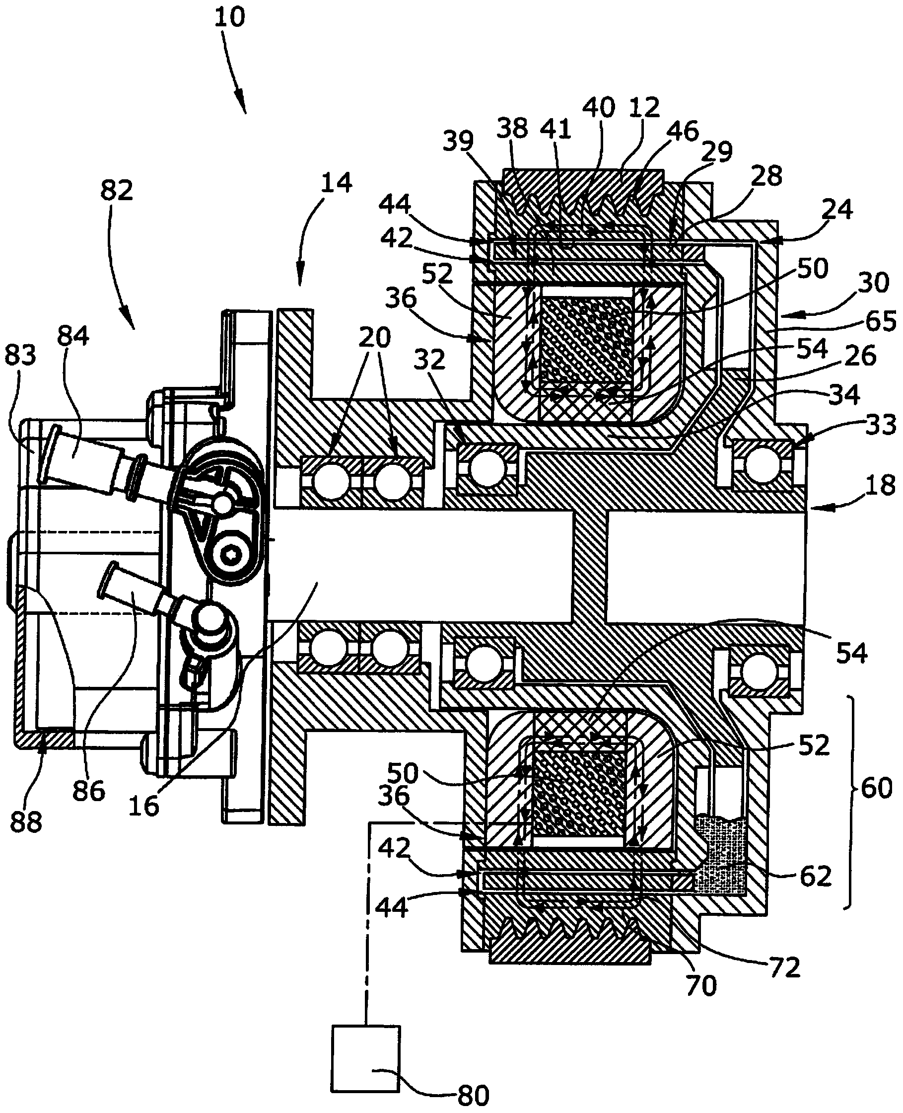
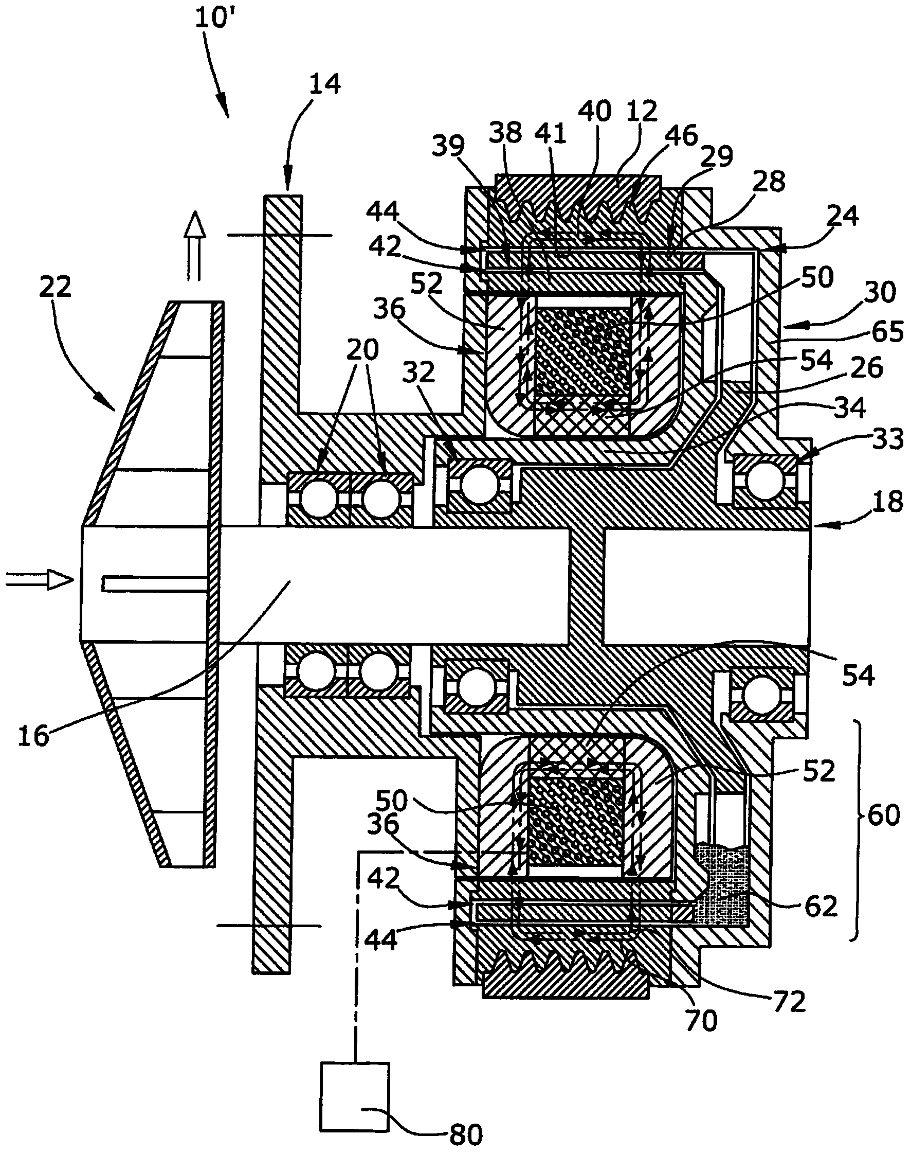
[0016] figure 1 A mechanical vehicle air pump 10 is shown, figure 2 A mechanical vehicle fluid pump 10' in the form of a coolant pump is shown. Both pumps 10, 10' are fluid pumps. The pneumatic pump 10 provides a gas, such as air, under pressure or provides vacuum to other engine components. The coolant pump 10' supplies liquid coolant to the internal combustion engine. The pumps 10, 10' are directly driven by the engine via a drive belt 12.

[0017] The pumps 10 each include a pump frame 14, 14' mountable to an engine block (not shown) of an engine. The pump frame 14, 14' supports the rotor shaft 16 of the pump rotor 18 by means of two roller bearings 20. The pump rotor 18 includes pump wheels 88 , 22 , a rotor shaft 16 and a rotatable clutch portion 24 which is permanently connected to the pump wheel 22 via the rotor shaft 16 .

[0018] The pneumatic pump 10 has a pump portion 82 including a pump housing 83 , a pump inlet 84 , a pump outlet 86 and a pump rot...


PUM


Abstract

The invention refers to a mechanical automotive fluidic pump (10) with a driving means (30) and a pump wheel (88), both being connectable by a hydraulic coupling (60) which is a magneto-rheological coupling (60). The coupling (60) is provided with a rotatable driving clutch element (39, 41) being permanently connected to the driving means (30), a rotatable driven clutch element (29) being permanently connected to the pump wheel (22) and a magneto-rheological liquid (62) filling a working gap (42, 44) between the two elements (29,39,41). According to the invention a magnet arrangement (36) with a permanent magnet (54) magnetically affecting the working gap (42, 44) and with an electromagnet (50) magnetically affecting the working gap (42, 44) are provided, whereby the electromagnet (50) is arranged to compensate the magnetic field (70) caused by the permanent magnet (54) in the working gap (42, 44) when the electromagnet (50) is active. If the electromagnet fails, the coupling remains engaged connected so that the coupling is failsafe.

Description

technical field [0001] The present invention relates to a mechanical automotive fluid pump directly mechanically driven by an internal combustion engine. The fluid pump may be an air pump or a liquid pump. Background technique [0002] Mechanical vehicle fluid pumps are directly driven by the internal combustion engine such that the rotational frequency of the pump is proportional to the rotational frequency of the engine. In order to have an improved adaptation of the pumping performance to the pumping performance requirement, the pump has a coupling. The pumping performance of the pump is adjusted by engaging and disengaging the coupling to connect or disconnect the pump wheel from an actuated drive, which may be a pulley driven by an engine. [0003] US2005 / 0188690A1 and US7422093B2 disclose a coupling for a vehicle hydraulic power steering pump, wherein the coupling is realized in the form of a magnetorheological coupling. The coupling has a driven clutch element perm...

Claims


Application Information

Patent Timeline
IPC IPC(8): F16D37/02
CPCF16D2037/004F16D37/02
Inventor N.诺维G.阿米尼奥
Owner PIERBURG PUMP TECH
Features
  • R&D
  • Intellectual Property
  • Life Sciences
  • Materials
  • Tech Scout
  • Unparalleled Data Quality
  • Higher Quality Content
  • 60% Fewer Hallucinations
Learn More