Coating machine capable of controlling coating amount of two surfaces and using method thereof

A technology of coating amount and coating machine, which is applied in the direction of coating, surface coating liquid device, etc., can solve the problems of high investment, large difference in coating amount between upper and lower surfaces, and large volume, so as to reduce production cost, The effect of reducing workload and high economic efficiency

Active Publication Date: 2013-12-18
ANGANG STEEL CO LTD
View PDF7 Cites 3 Cited by
  • Summary
  • Abstract
  • Description
  • Claims
  • Application Information

AI Technical Summary

Problems solved by technology

[0002] Coating machines are widely used in the fields of steel, printing and dyeing, etc. According to the structure, they are divided into: three-roll single-track coating machine, three-roll slide rail accumulation coating machine, horizontal three-roll reverse coating machine, simple two-roll coating machine, etc. , the three-roll coating machine can realize independent adjustment of the coating amount on the upper and lower surfaces, but the equipment volume is large and the investment is high. Although the simple two-roll coating machine has a simple structure and low cost, it is prone to large differences in the coating amount on the upper and lower surfaces. , need unloading roller adjustment

Method used


Image

  • Coating machine capable of controlling coating amount of two surfaces and using method thereof

Examples


Embodiment Construction

[0017] The specific embodiment of the present invention is further described below in conjunction with accompanying drawing:

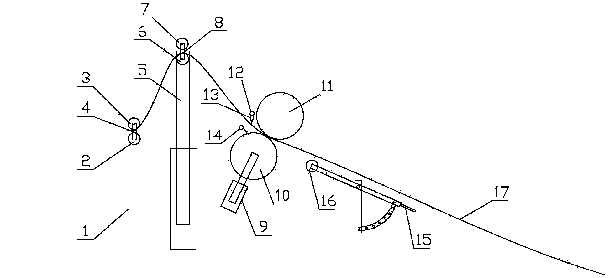
[0018] Such as figure 1 As shown, a coating machine with controllable coating amount on both sides of the present invention includes a fixed base 1, a lower roller 2, an upper roller 3, a limiter 4, a cylinder 5, a lower roller 6, and an upper roller 2 7. Limit two 8, cylinder two 9, lower roller three 10, upper roller three 11, header one 12, scraper 13, header two 14, moving device 15 and idler roller 16, the fixed seat 1 The top is provided with a lower roller 2 and an upper roller 3, the lower roller 2 and the upper roller 3 are connected by a limiter 4, the top of the cylinder 5 is provided with a lower roller 6 and an upper roller 7, and the lower roller Two 6 and upper roller two 7 are connected by limit two 8, lower roller three 10 and upper roller three 11 are arranged on the top of cylinder two 9, header one 12 is respectively arranged on th...


PUM


Abstract

The invention relates to a coating machine capable of controlling coating amount of two surfaces. The coating machine comprises a fixed seat, a lower roll 1, an upper roll 1, a limiter 1, an air cylinder 1, a lower roll 2, an upper roll 2, a limiter 2, an air cylinder 2, a lower roll 3, an upper roll 3, a collecting pipe 1, a scratch board, a collecting pipe 2, a carrying device and a touch roll, wherein the top end of the fixed seat is provided with the lower roll 1 and the upper roll 1, and the lower roll 1 is connected with the upper roll 1 through the limiter 1; the top end of the air cylinder 1 is provided with the lower roll 2 and the upper roll 2, and the lower roll 2 is connected with the upper roll 2 through the limiter 2; the top end of the air cylinder 2 is provided with the lower roll 3 and the upper roll 3, and one sides of the lower roll 3 and the upper roll 3 are respectively provided with the collecting pipe 1 and the collecting pipe 2, and the scratch board is arranged at the collecting pipe 1; one end of the carrying device is provided with the touch roll. Compared with the prior art, the coating machine has the beneficial effects of being simple in structure, being scientific and practical, effectively controlling the amount coating of ]the upper surface and the lower surface of belt steel, reducing workload, improving working efficiency, reducing production cost, and creating a high economic benefit for enterprises.

Description

technical field [0001] The invention relates to the technical field of cold-rolled silicon steel, in particular to a coating machine with controllable coating amount on both sides and a use method thereof. Background technique [0002] Coating machines are widely used in the fields of steel, printing and dyeing, etc. According to the structure, they are divided into: three-roll single-track coating machine, three-roll slide rail accumulation coating machine, horizontal three-roll reverse coating machine, simple two-roll coating machine, etc. , the three-roll coating machine can realize the independent adjustment of the coating amount on the upper and lower surfaces, but the equipment volume is large and the investment is high. Although the simple two-roll coating machine has a simple structure and low cost, it is prone to large differences in the coating amount on the upper and lower surfaces. , need unloading roller adjustment. [0003] Invention patent CN200610147268.3, a...

Claims


Application Information

Patent Timeline
Patent Type & Authority Applications(China)
IPC IPC(8): B05C9/04B05C11/00
Inventor 王铁姜福建李志坚李维彪胡洪旭
Owner ANGANG STEEL CO LTD
Why Eureka
Try Eureka