Design and manufacturing method of light guide points on light guide plate

A technology of light guide dots and manufacturing methods, which is applied in manufacturing tools, laser welding equipment, optics, etc. It can solve problems such as dot drift, multiple dark areas and bright areas, and uneven illumination of light guide plates, so as to achieve good uniformity and reduce abnormalities effect of change

Inactive Publication Date: 2013-12-18
瑞安市博业激光应用技术有限公司
View PDF7 Cites 8 Cited by
  • Summary
  • Abstract
  • Description
  • Claims
  • Application Information

AI Technical Summary

Problems solved by technology

However, at present, when lasers are used to process the light guide dots on the light guide plate, the dots are generally processed line by line, so that once there is interference during the processing, or due to the influence of factors such as temperature and time, the processed dots will be damaged. Drift occurs, so that the illumination of the light guide plate is not uniform enough, and there are more dark or bright areas

Method used


Image

  • Design and manufacturing method of light guide points on light guide plate
  • Design and manufacturing method of light guide points on light guide plate
  • Design and manufacturing method of light guide points on light guide plate

Examples


Embodiment Construction

[0016] The present invention will be described in further detail below in conjunction with the accompanying drawings and specific embodiments.

[0017] The invention provides a method for designing and manufacturing light guide dots on a light guide plate, comprising the following steps:

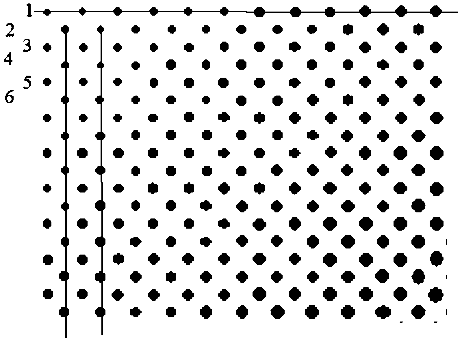
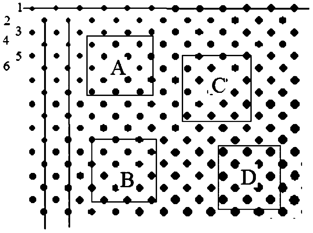
[0018] (1) Design the distribution position and size of the light guide network points, control the time of laser dots by fixing the power of the laser or control the size of the points by fixed time and different laser power; according to the shape of the light guide plate and the lamp used Depending on the quantity and the applied position, the light guide dots arranged in different shapes are designed, the spacing between the light guide dots will change in a certain way, and the size of each light guide dot will also change in a certain way.

[0019] At the same time, divide all the light guide network points into several light guide network point rows, such as figure 1 shown. In order...


PUM


Abstract

The invention provides a design and manufacturing method of light guide points on a light guide plate. The design and manufacturing method includes 1, designing distributing position and size of a point of the light guide points, and controlling size of the point through laser lighting time or by controlling power of laser; meanwhile, dividing all the light guide points into several light guide point lines; 2, dividing point image into several areas, processing the light guide points among each area and inside the areas randomly during the process; or processing one by one the light guide points in odd number lines among the light guide point lines; after all the light guide points in the odd number lines are processed, processing one by one the light guide points in even number lines among the light guide point lines along the vertical direction until all the light guide points are processed. With the design and manufacturing method, possible influence on results such as electromagnetic interference and equipment temperature flutter and drift during pointing process is overcome, influence on light guide point processing from external factors can be minimized, and uniformity of the processed light guide plate is good.

Description

technical field [0001] The invention belongs to the field of laser processing, and in particular relates to a method for designing and manufacturing light guide dots on a light guide plate. Background technique [0002] Light guide plate lighting technology was first invented in 1986 by Japan Minto Corporation, and it is currently the mainstream method for backlighting LCD screens of notebook computers. Its working principle is to use the PMMA transparent light guide plate to introduce the pure white light emitted by the cold cathode fluorescent tube (line light source) from the end face of the transparent plate and diffuse it to the entire plate surface. Reflection, emitted from the plate surface (working surface) perpendicular to the incident surface of the light source. The light guide plate lighting uses the principle of total reflection of light on the interface of the transparent plate to deflect the light incident on the end surface by 90° and emit it from the front,...

Claims


Application Information

Patent Timeline
Patent Type & Authority Applications(China)
IPC IPC(8): B23K26/36G02B6/00
Inventor 任心波张一瑞陈卫国
Owner 瑞安市博业激光应用技术有限公司
Why Eureka
Try Eureka