Vehicle-mounted water cutting system

A cutting system and vehicle-mounted technology, which is applied to used abrasive processing devices, abrasives, metal processing equipment, etc., can solve problems such as the inability of the equipment to function effectively, and achieve the effect of rapid movement.

Active Publication Date: 2013-12-18
纪新刚
View PDF6 Cites 11 Cited by
  • Summary
  • Abstract
  • Description
  • Claims
  • Application Information

AI Technical Summary

Problems solved by technology

In this case, many functions of the equipment cannot be effectively played

Method used


Image

  • Vehicle-mounted water cutting system
  • Vehicle-mounted water cutting system
  • Vehicle-mounted water cutting system

Examples


specific Embodiment 1

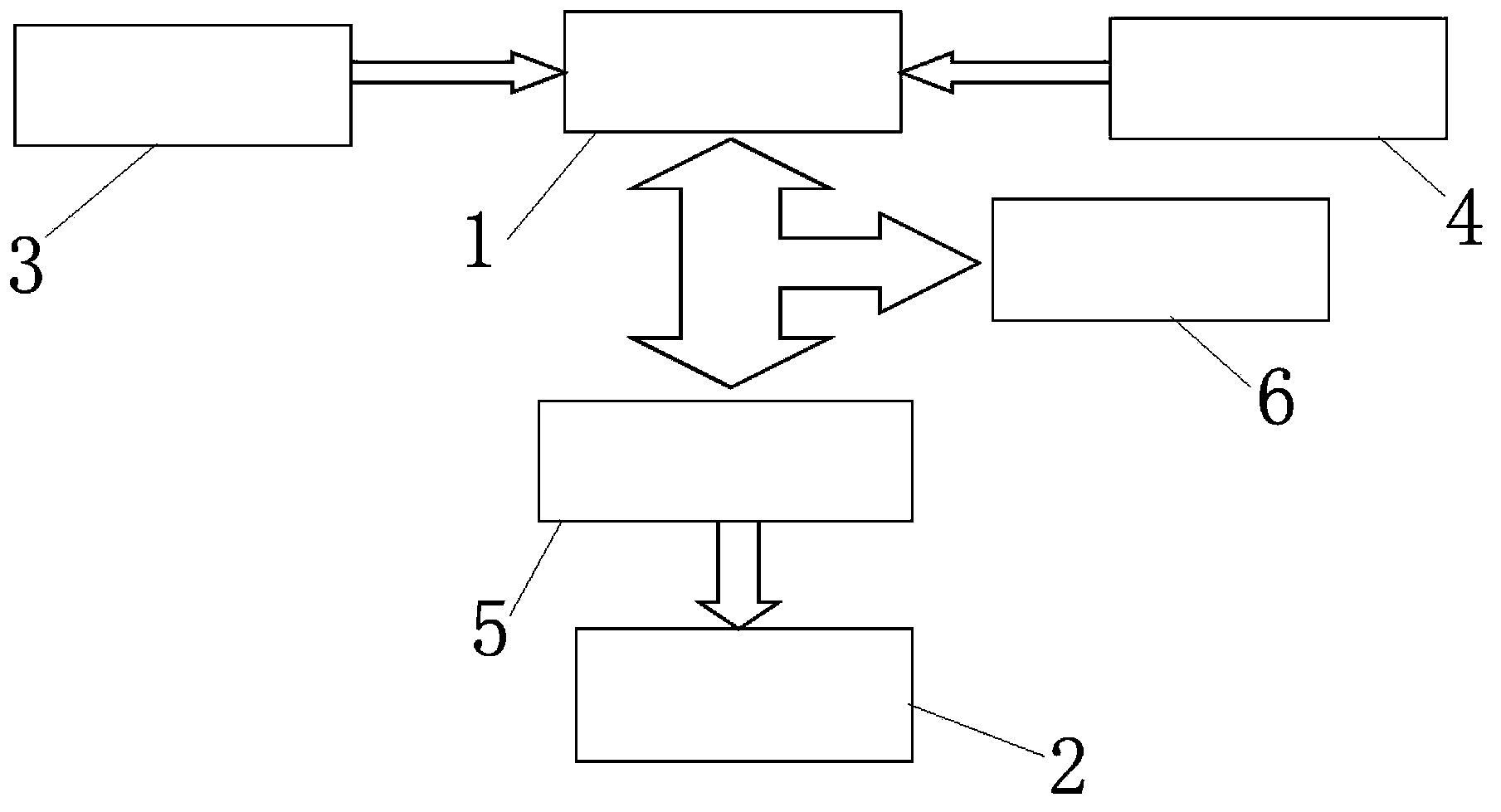
[0018] Such as figure 2 As shown, the vehicle-mounted water cutting system described in the embodiment of the present invention includes a water booster system 1 and a cutting device 2, and the water booster system 1 is connected with an engine power take-off 3 and a water supply system 4, and the water booster system An abrasive mixing device 5 is provided between the system 1 and the cutting device 2 , and an overpressure protection device 6 is provided between the abrasive mixing device 5 and the water pressurization system 1 .

[0019] The water pressurization system 1 includes a supercharger 7, a hydraulic pump 8 and a water pump 9. One end of the supercharger 7 is connected to the cutting device 2, and the other end of the supercharger 7 is connected to a cooling device through a reversing valve 10, respectively. 11 and the hydraulic pump 8 are connected to the water tank 12 through the water pump 9, the hydraulic pump 8 and the cooler 11 are connected to the vehicle fu...

specific Embodiment 2

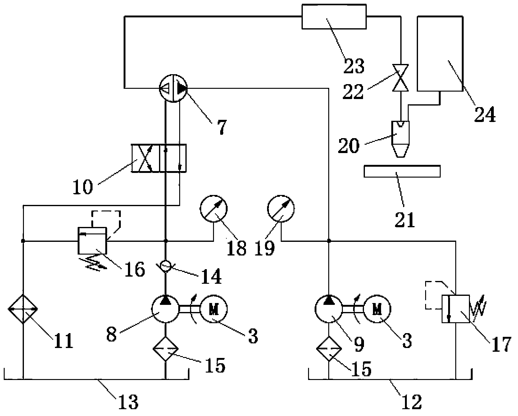
[0023] Such as image 3 As shown, the vehicle-mounted water cutting system described in the embodiment of the present invention includes a water booster system 1 and a cutting device 2, and the water booster system 1 is connected with an engine power take-off 3 and a water supply system 4, and the water booster system An abrasive mixing device 5 is provided between the system 1 and the cutting device 2 , and an overpressure protection device 6 is provided between the abrasive mixing device 5 and the water pressurization system 1 .

[0024]The water pressurization system 1 includes a supercharger 7, a hydraulic pump 8 and a water pump 9. One end of the supercharger 7 is connected to the cutting device 2, and the other end of the supercharger 7 is connected to a cooling device through a reversing valve 10, respectively. 11 and the hydraulic pump 8 are connected to the water tank 12 through the water pump 9, the hydraulic pump 8 and the cooler 11 are connected to the vehicle fuel...

specific Embodiment 3

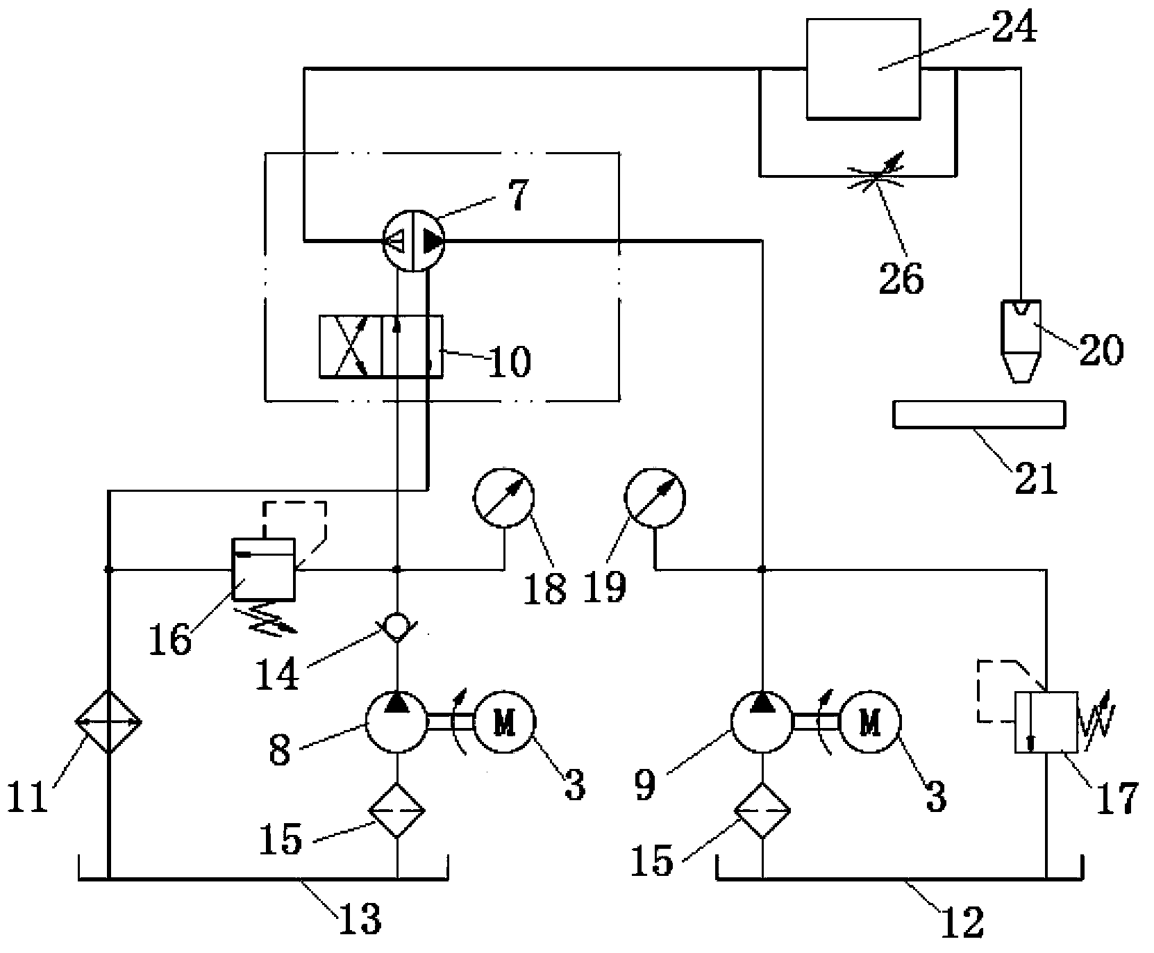
[0028] Such as Figure 4 As shown, the vehicle-mounted water cutting system described in the embodiment of the present invention includes a water booster system 1 and a cutting device 2, and the water booster system 1 is connected with an engine power take-off 3 and a water supply system 4, and the water booster system An abrasive mixing device 5 is provided between the system 1 and the cutting device 2 , and an overpressure protection device 6 is provided between the abrasive mixing device 5 and the water pressurization system 1 .

[0029] The water pressurization system 1 includes a high-pressure water pump 25 and a water pump 9, the high-pressure water pump 25 and the water pump 9 are connected to the engine power take-off 3, and one end of the high-pressure water pump 25 is connected to the cutting device through a one-way valve 14 2. The other end of the high-pressure water pump 25 is connected in series with one end of the water pump 9, and the other end of the water pum...


PUM


Abstract

The invention relates to a vehicle-mounted water cutting system. The vehicle-mounted water cutting system comprises a water pressurization system and a cutting system, wherein the water pressurization system is connected with an engine power takeoff and a water supply system; a grinding material mixing device is arranged between the water pressurization system and the cutting device; an overpressure protection device is arranged between the grinding material mixing device and the water pressurization system. The vehicle-mounted water cutting system has the beneficial effects that the vehicle-mounted water cutting system is directly configured and arranged on a vehicle by adopting a modular structure; an original engine of the vehicle is utilized as power, and thus the inconvenience that the power is additionally configured is prevented; the whole equipment is arranged and integrated on the vehicle, and is flexible and quick to move; without power supply or other auxiliary facilitates, the work in any environment can be realized; the cutting process is free of high temperature, open fire or static electricity, the molecular structure of a cut object is not damaged, and thermal deformation and chemical transformation can be avoided.

Description

technical field [0001] The invention relates to a vehicle-mounted water cutting system. Background technique [0002] The usual water cutting equipment is in the form of a single body, which is a fixed single device, and usually uses a motor as power to integrate it into the device. The heavy motor cannot move quickly and flexibly, and needs power supply or other auxiliary facilities during use, so it cannot be used in any environment. In addition, equipment that is not easy to move cannot be used for cleaning the surface of various materials and the inside of holes. Such as: corrosion, attachments, paint, etc. on the metal surface. Surface treatment of various materials such as dirt cleaning on the surface of stone materials, cleaning of attachments on the surface of hulls, and cleaning of airstrips. And for water jet perforation fire extinguishing, such as: fire extinguishing through walls in confined spaces in fire protection, in the case of fires in closed environment...

Claims


Application Information

Patent Timeline
Patent Type & Authority Applications(China)
IPC IPC(8): B24C3/02B24C7/00B24C9/00
Inventor 纪新刚宋新伟
Owner 纪新刚
Why Eureka
Try Eureka