
Self-locking type spray cap

A self-locking, spray cap technology, applied in the direction of liquid distribution, etc., can solve the problems of inconvenient installation and disassembly, inconvenient use, hidden safety hazards, etc., and achieve the effect of beautiful appearance, smooth outer wall and convenient installation

Active Publication Date: 2013-12-18
ZHONGSHAN MEIJIESHI PACKAGING PROD
View PDF4 Cites 14 Cited by
  • Summary
  • Abstract
  • Description
  • Claims
  • Application Information

AI Technical Summary

Problems solved by technology

Existing spray caps that are used for filling sprays or insecticides do not have a locking mechanism. After the spray cap packaging is removed, as long as the head is pressed, the spray or insecticides will be sprayed from the nozzle. There are certain security risks
[0003] In order to overcome this problem, there is also a locking mechanism provided in the spray cover at present, such as a spray cover disclosed in US Patent US20050017027A1. The head is rotated to a specific position, that is, the positioning block falls into the relief groove, and the head can be pressed down, but this design is not only complicated in structure, it is inconvenient to install and disassemble, and if the head is rotated during use, It is easy to change the locked or unlocked state of the spray cap, which is not very convenient to use

Method used


Image

  • Self-locking type spray cap
  • Self-locking type spray cap
  • Self-locking type spray cap

Examples


Embodiment Construction

[0029] The present invention will be further described below in conjunction with accompanying drawing description and specific embodiment:

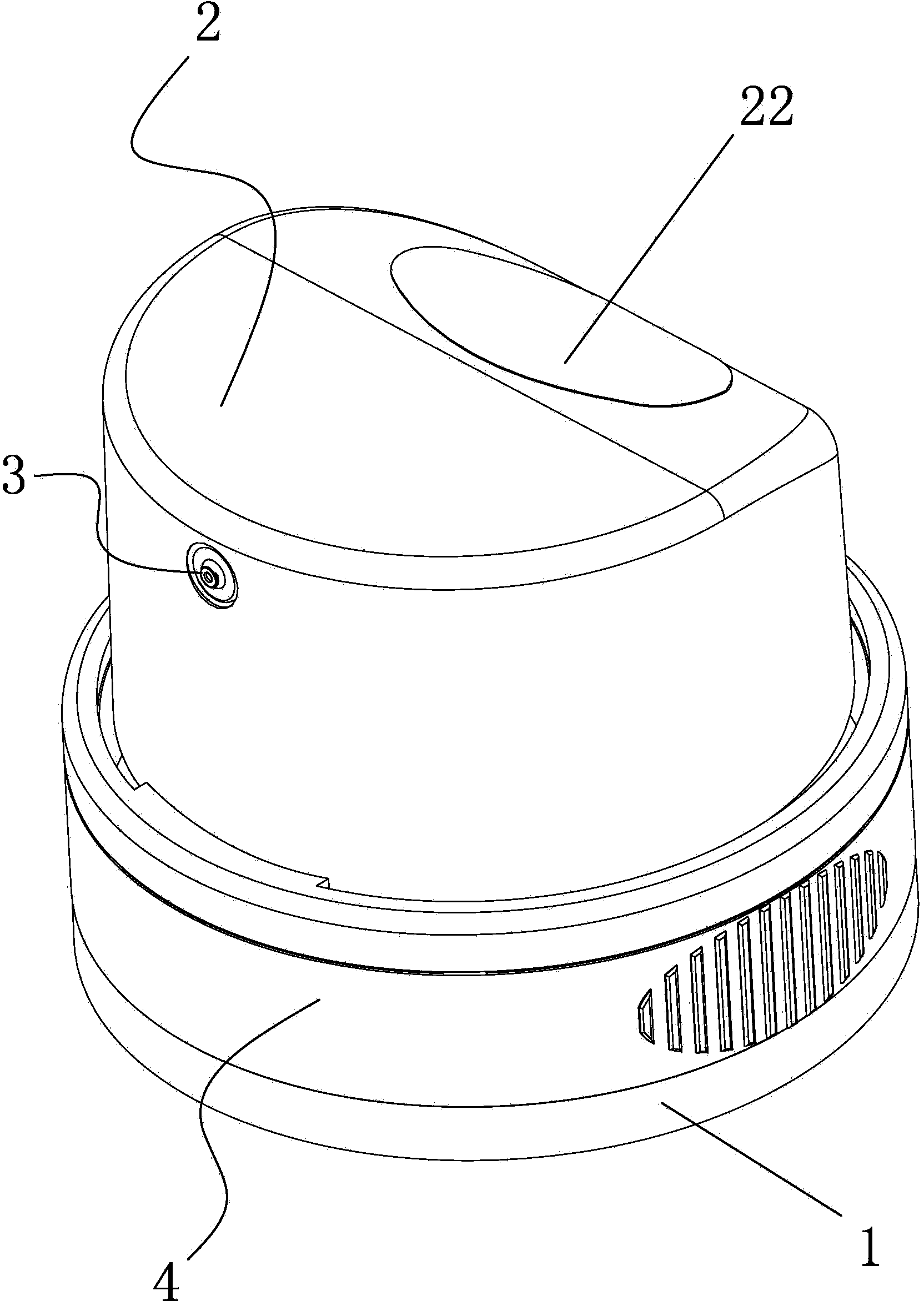
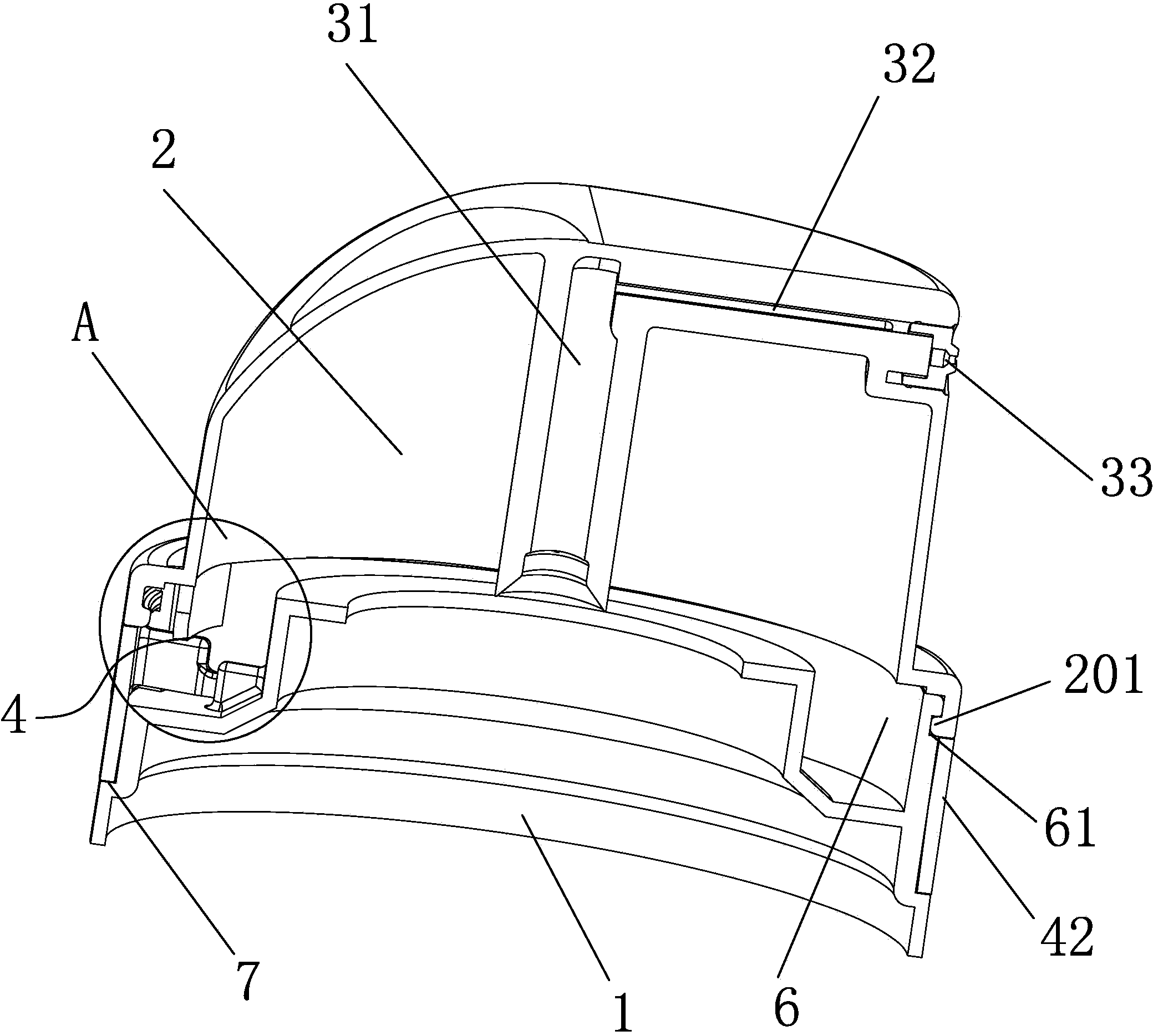
[0030] Such as Figures 1 to 9 The shown self-locking spray cap includes a base 1, a press head 2 is connected to the base 1, a nozzle 3 is provided on the press head 2, and a nozzle 3 is arranged between the base 1 and the press head 2. There is a press head locking mechanism 4 that can prevent the press head 2 from pressing down and moving.

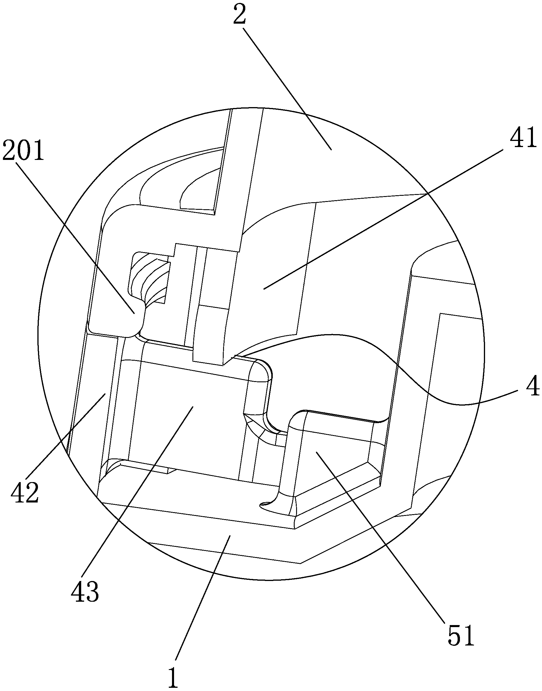
[0031] Such as figure 2 and 3 As shown, the press head locking mechanism 4 in the present invention includes a positioning block 41 extending downward inside the press head 2 , and a lock ring 42 is provided between the press head 2 and the base 1 on the inner wall of the lock ring 42 There is a lock tongue 43 that can be pressed against the lower end of the positioning block 41 so as to prevent the press head 2 from moving downwards. The base 1 is provided with a limiting groove 44. Inside sl...


PUM


Abstract

The invention discloses a self-locking type spray cap. The self-locking type spray cap comprises a base, wherein a press head is connected to the base, and a spray nozzle is arranged on the press head. The self-locking type spray cap is characterized in that a press head locking mechanism capable of preventing the press head from being pressed down and moved is arranged between the base and the press head; a limit mechanism capable of preventing the press head locking mechanism from switching optionally between a locking state and an unlocking state is arranged on the base. The invention aims to solve the shortages in the prior art, and provides the self-locking type spray cap which is simple in structure, convenient to use and install, and good in locking effect.

Description

technical field [0001] The invention relates to a self-locking spray cover. Background technique [0002] Sprays or insecticides filled at present are generally sprayed by the spray cover control valve mechanism installed on the top of the container jar during use. Existing spray caps that are used for filling sprays or insecticides do not have a locking mechanism. After the spray cap packaging is removed, as long as the head is pressed, sprays or insecticides will be sprayed from the nozzle. There are certain security risks. [0003] In order to overcome this problem, there is also a locking mechanism provided in the spray cover at present, such as a spray cover disclosed in US Patent US20050017027A1. The head is rotated to a specific position, that is, the positioning block falls into the relief groove, and the head can be pressed down, but this design is not only complicated in structure, it is inconvenient to install and disassemble, and if the head is rotated during u...

Claims


Application Information

Patent Timeline
IPC IPC(8): B65D83/22
Inventor 李军
Owner ZHONGSHAN MEIJIESHI PACKAGING PROD
Learn More