a retaining wall

A retaining wall and front wall technology, which is applied in water conservancy projects, artificial islands, underwater structures, etc., can solve the large stress difference between the front toe and heel of the floor, increase the engineering volume of the working face, increase the engineering volume of the retaining wall, etc. problems, to achieve the effect of improving anti-sliding, reducing engineering cost, and improving the stress condition of foundation and structure

Active Publication Date: 2016-01-20
中山市水利水电勘测设计咨询有限公司
View PDF3 Cites 0 Cited by
  • Summary
  • Abstract
  • Description
  • Claims
  • Application Information

AI Technical Summary

Problems solved by technology

On the one hand, widening the floor will increase the engineering volume of the retaining wall itself, and will also increase the engineering volume of the excavation of the working face and backfilling behind the wall, which is less economical; using block stone prisms as backfilling behind the wall requires mining rocks, which are harmful to the environment
In addition, due to the partial load of the structure in the traditional retaining wall structure, the stress difference between the front toe and the back heel of the floor is very large. When the stress of the front toe exceeds the bearing capacity of the foundation, foundation treatment is required

Method used


Image

  • a retaining wall
  • a retaining wall
  • a retaining wall

Examples


Embodiment Construction

[0012] The present invention will be further described below in conjunction with the accompanying drawings and specific embodiments.

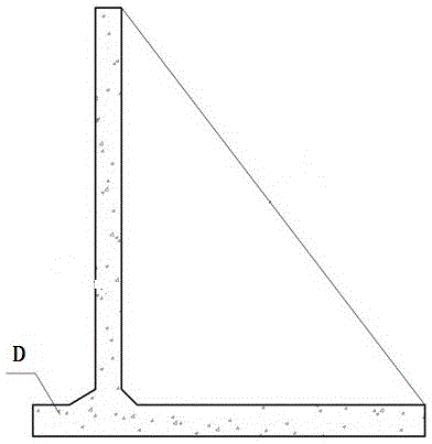
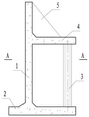
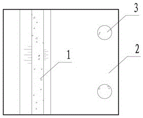
[0013] Such as figure 1 As shown, the retaining wall includes a front wall 1, a base plate 2, a column 3 and an unloading platform 4, the bottom edge of the front wall is fixedly connected with the base plate, the unloading platform 4 is connected horizontally with the upper side of the front wall, and the column is vertical It is arranged on the bottom plate and the upper end is supported and connected with the lower side of the unloading platform. The unloading platform can choose to use some ribs 5 to connect with the front wall according to the size of the upper load; the column 3 is a column or a square column (circle is better). The unloading platform 4 transmits the upper load to the bottom plate 2 through the column 3 to reduce the horizontal pressure of the upper load on the front wall 1 .

[0014] The front wall 1 is generally desig...


PUM


Abstract

The invention relates to a retaining wall, in particular to a middle corridor type retaining wall. The retaining wall comprises a front wall, base plates, upright columns and an unloading platform, wherein the bottom side of the front wall is fixedly connected with the base plates, the unloading platform is horizontally connected with one side face of the upper part of the front wall, the upright columns are vertically arranged on the base plates, and the upper ends of the upright columns are connected with the lower side face of the unloading platform. According to the retaining wall disclosed by the invention, by utilizing the unloading platform, loads of the upper part are conveyed onto the base plates through the upright columns, and the soil body below a platform does not bear the loads of the upper part, so that the horizontal soil pressure to the front wall is reduced, even the effect that the horizontal soil pressure is reduced by 25% can be realized; therefore the anti-sliding and anti-collapsing performances of the retaining wall are improved, the unbalance loading degree of the structure of the retaining wall is reduced, and the stress situations of the foundation and the structure of the retaining wall are improved. According to the retaining wall disclosed by the invention, the foundation treatment is not needed, the volume of earthwork is reduced, the problems of the engineering structure are solved, and the cost of the engineering is also reduced; the damage by quarrying the mountain to the environment is avoided.

Description

technical field [0001] The invention relates to the field of retaining walls, in particular to a retaining wall with an inner corridor structure. Background technique [0002] In the construction of water transportation and water conservancy, etc., it is necessary to set up retaining walls to realize the use function or the safety of the slope structure, or to save space. Traditional retaining wall structures such as figure 1 As shown, in order to achieve overall anti-sliding and anti-tilting stability, the bottom plate D is usually widened to increase resistance, or block stone prisms with large internal friction angles are used as backfilling behind the wall to reduce the horizontal earth pressure behind the wall. On the one hand, widening the floor will increase the engineering volume of the retaining wall itself, and will also increase the engineering volume of the excavation of the working face and backfilling behind the wall, which is less economical; using block ston...

Claims


Application Information

Patent Timeline
Patent Type & Authority Patents(China)
IPC IPC(8): E02D29/02
Inventor 徐志栓陶源
Owner 中山市水利水电勘测设计咨询有限公司
Why Eureka
Try Eureka