Heat pump system

A heat pump system and compressor technology, applied in heat pumps, lighting and heating equipment, damage protection, etc., can solve the problems of difficult cost control, a lot of expenses, inconvenient maintenance and repair, etc., and achieve the effect of cost saving

Inactive Publication Date: 2013-12-18
JOHNSON CONTROLS AIR CONDITIONING & REFRIGERATION WUXI +1
View PDF6 Cites 2 Cited by
  • Summary
  • Abstract
  • Description
  • Claims
  • Application Information

AI Technical Summary

Problems solved by technology

In this heat pump system, each V-shaped coil is individually equipped with an expansion valve and an independent hot gas injection solenoid valve, and when the V-shaped coil is used as an evaporator, it also needs to be equipped with a main suction valve. The composition of the heat pump is complicated, it is not convenient for daily maintenance and repair, and the establishment of such a heat pump system requires a lot of money, and the cost is difficult to control

Method used


Image

  • Heat pump system

Examples


Embodiment Construction

[0020] In the following description, numerous specific details are given in order to provide a more thorough understanding of the present invention. It will be apparent, however, to one skilled in the art that the present invention may be practiced without one or more of these details. In other examples, some technical features known in the art are not described in order to avoid confusion with the present invention.

[0021] In order to provide a thorough understanding of the present invention, the detailed structure will be set forth in the following description. It is evident that the practice of the invention is not limited to specific details familiar to those skilled in the art. Preferred embodiments of the present invention are described in detail below, however, the present invention may have other embodiments besides these detailed descriptions.

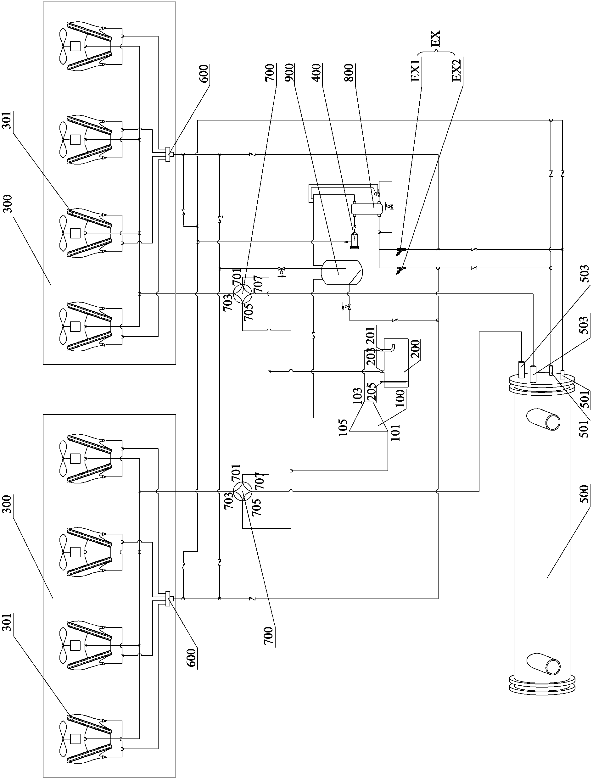
[0022] The invention discloses a heat pump system, such as figure 1 As shown, the heat pump system includes a main cool...


PUM


Abstract

The invention discloses a heat pump system comprising a main refrigerating line and a plurality of refrigerating branches. The main refrigerating line comprises a compressor unit; each refrigerating branch comprises coil units, evaporator units, a reversing unit and a throttler unit, and the quantity of the coil units is equal to that of the evaporator units. The compressor unit of the main refrigerating line is connected with the reversing unit of each refrigerating branch to deliver high-temperature high-pressure air to the reversing unit and receive air from the reversing unit; after receiving the high-temperature high-pressure air from the compressor unit, the reversing unit delivers the high-temperature high-pressure air to the coil units or the evaporator units according to operation modes of the heat pump system. Direction of the high-temperature high-pressure air is controlled by the reversing units, so that cost of the whole heat pump system is saved and fractional defrosting can be implemented.

Description

technical field [0001] The invention relates to the technical field of heat pump systems, in particular to a heat pump system. Background technique [0002] The heat pump system absorbs low-grade heat energy from the outdoor environment during heating, and then transports the heat to the indoor side to meet people's needs for heating in winter and using hot water. When the surface temperature of the evaporator of the heat pump system is lower than 0°C, the moisture in the air will condense into frost on the surface of the evaporator. Air resistance, even completely blocking the air circulation channel, makes the air source heat pump system unable to continuously heat. Therefore, the defrosting control of the heat pump system in the heating mode is a very important link. [0003] At present, many heat pump systems are defrosting in a step-by-step defrosting method. In the heat pump system using step-by-step defrosting, all the coils are decomposed into several independent ...

Claims


Application Information

Patent Timeline
IPC IPC(8): F25B30/02F25B47/02
Inventor 李静王利杜文涛姜爱华周月娴
Owner JOHNSON CONTROLS AIR CONDITIONING & REFRIGERATION WUXI
Why Eureka
Try Eureka