Refrigerating equipment

A refrigeration equipment and cabinet technology, applied in the field of refrigeration equipment, can solve the problems of poor food storage effect, affecting refrigeration effect, high power consumption, etc., and achieve the effect of easy opening, low cost, and difficult opening

Active Publication Date: 2013-12-18
HEFEI HUALING CO LTD
View PDF7 Cites 9 Cited by
  • Summary
  • Abstract
  • Description
  • Claims
  • Application Information

AI Technical Summary

Problems solved by technology

[0002] Leakage of cold air from refrigeration equipment will affect the cooling effect, consume a lot of energy and electricity, poor food storage effect, and condensation phenomenon at the same time

Method used


Image

  • Refrigerating equipment
  • Refrigerating equipment
  • Refrigerating equipment

Examples


Embodiment 1

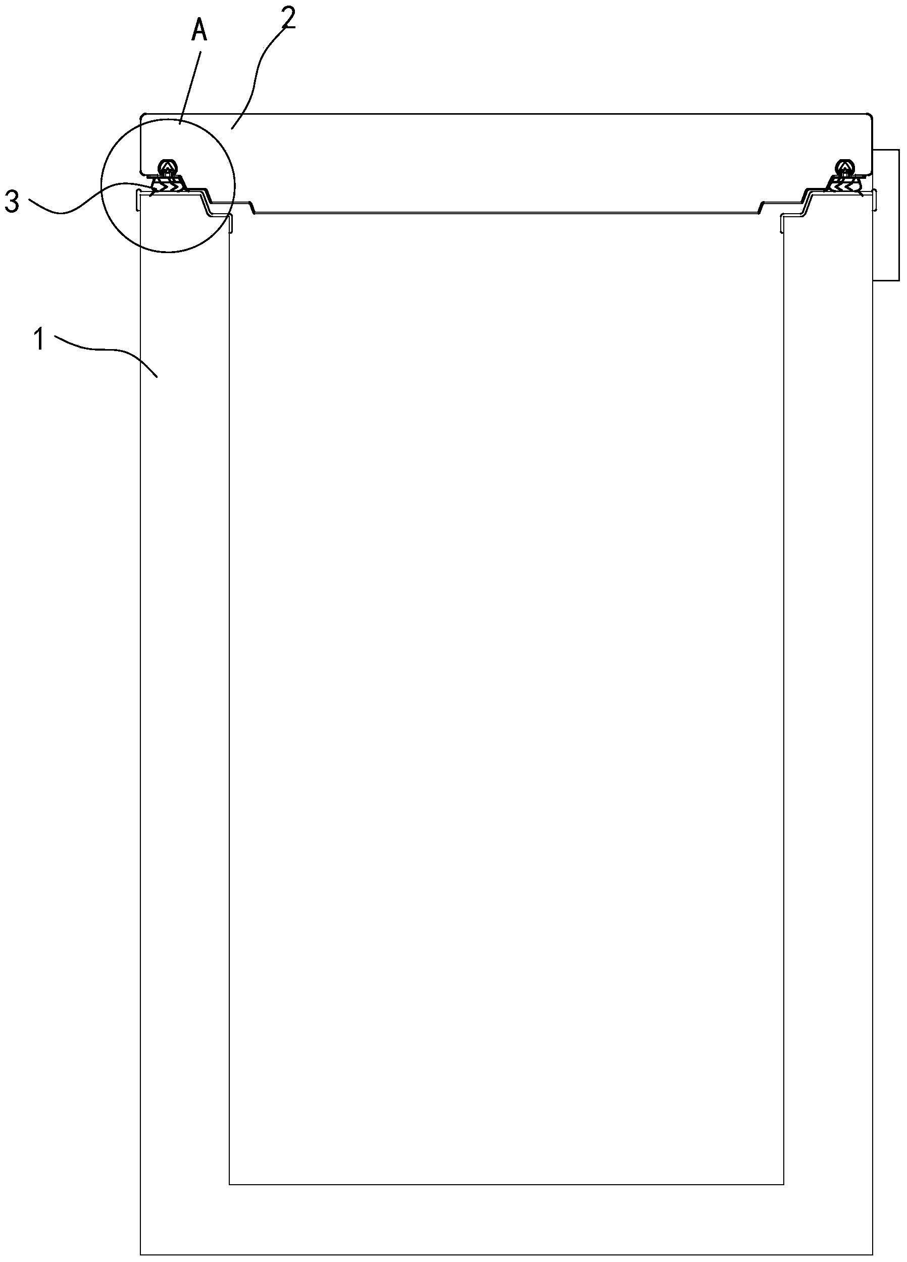
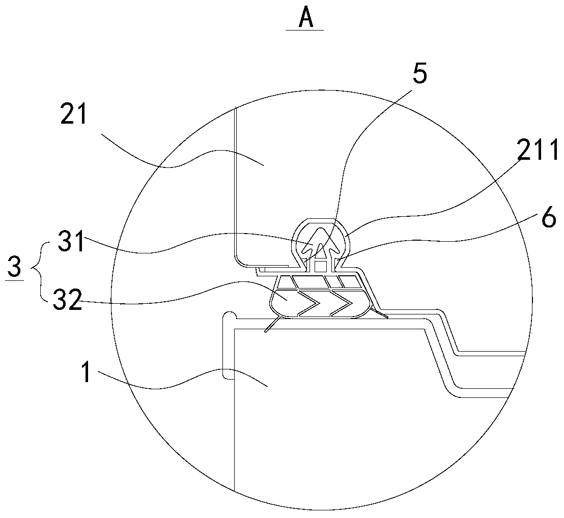
[0052] Such as Figure 1-Figure 8 As shown, in this embodiment, both the buckle end 311 and the connecting section 312 have a hollow portion 33 . Thus, the door seal 3 has a certain degree of elasticity, so that the door seal 3 and the groove 211 are tightly closed after the door body 2 is closed. In addition, the refrigeration device according to the invention can be made cost-effective.

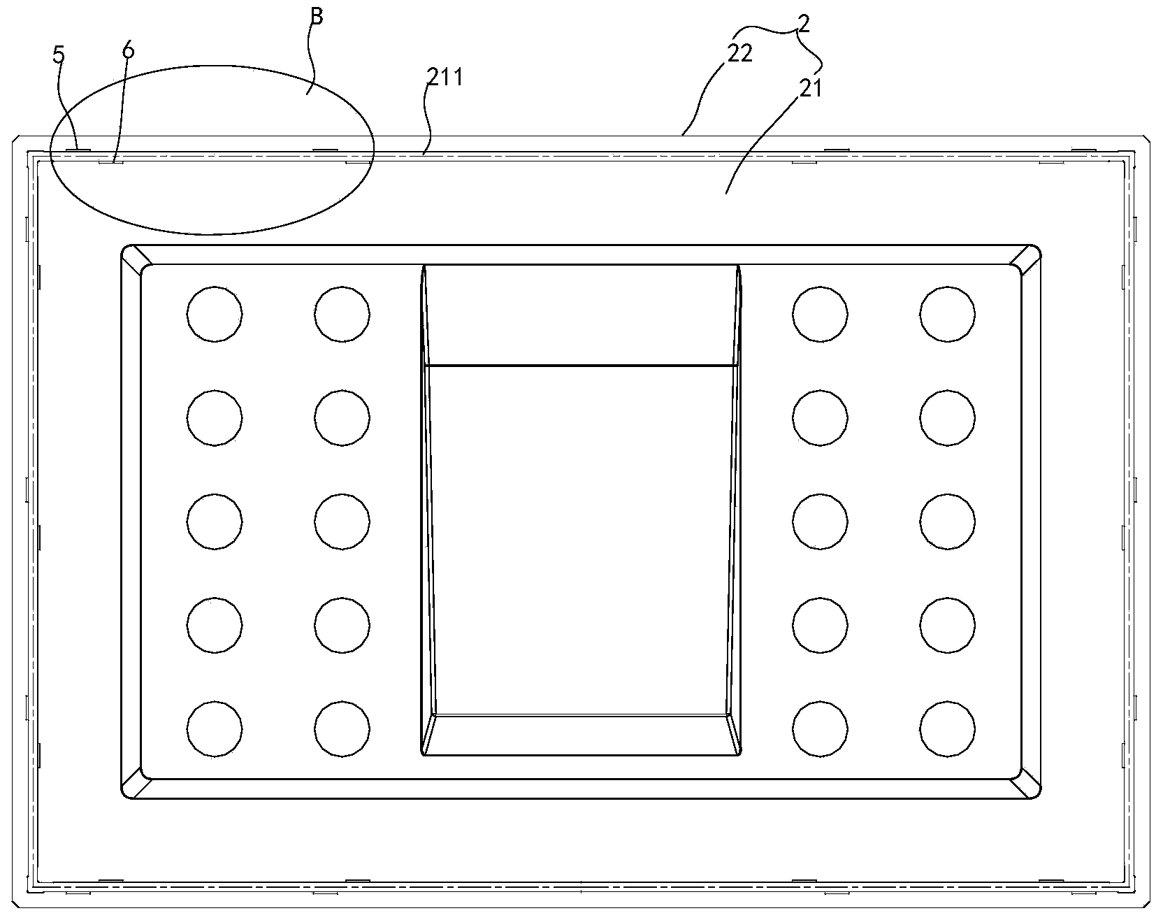
[0053] According to the refrigeration equipment of the present invention, it further includes a first boss portion 5 and a second boss portion 6, and the first boss portion 5 and the second boss portion 6 are correspondingly arranged in a part of the groove 211, as Figure 1-Figure 2 , Figure 7 and Figure 8 As shown, the buckle end 311 extends into the groove 211, and its two ends respectively stop against the first boss part 5 and the second boss part 6, wherein when the door body 2 receives an upward external force, the ventilation The channel 4 is formed between the connecting sect...

Embodiment 2

[0065] refer to Figure 9-Figure 11 , in the embodiment, both the buckle end 311 and the connection section 312 are solid, and the axial length of the connection section 312 is greater than the axial length of the buckle end 311 . in, Figure 9-Figure 11 Regions A, B and C represented by figure 2 , Figure 6 and Figure 8 The regions represented are similar.

[0066] When the door body 2 receives an upward external force, the air passage 4 is formed between the connecting section 312 , the buckle end 311 and the groove 211 .

[0067] Compared with the first embodiment, the cross-sectional dimension of the connecting section 312 in the refrigeration equipment of the second embodiment is reduced and the axial length is increased, that is, the difference between the cross-sectional dimension L2 of the connecting section 312 and the minimum cross-sectional dimension D of the groove 211 larger, and the axial length of the connecting section 312 is larger, so when the door bod...


PUM


Abstract

The invention discloses refrigerating equipment, which comprises a box body, a door body and a door seal, wherein the top of the box body is open; the door body is used for opening and closing the box body; the door body is connected to the top of the box body in a pivoting way; the door body comprises a door liner; a groove which is depressed upwards is formed on the lower surface of the door liner; the groove is close to the outer edge of the lower surface of the door liner and surrounds the outer edge by a circle; the upper part of the door seal is clamped in the groove; when the door body is closed, the lower part of the door seal is sealed in a way of being pressed against the top of the box body; and when upward external force is applied to the door body, a ventilation channel is formed between the door seal and the groove. According to the refrigerating equipment disclosed by the invention, the upper part of the door seal is clamped in the door liner and can move relative to the door liner to form the ventilation channel to prevent external air from entering the box body, so that balance of internal and external air pressures of the box body is realized, the door is very easy to open, and the air tightness between the door body and the box body is not influenced when the door body is closed once again.

Description

technical field [0001] The invention relates to a refrigeration device. Background technique [0002] Leakage of cold air from refrigeration equipment will affect the cooling effect, consume a lot of energy, poor food storage, and condensation. In the prior art, in order to reduce the leakage of cold air, the gap between the door liner of the refrigerator product and the outer frame of the box is designed to be small, and the sealing performance of the door seal is good. [0003] However, since the hot air from the outside enters the freezer after opening the door, and the air temperature drops after closing the door, there is a certain pressure difference inside and outside the freezer, and the airtightness is good, so the door is tightly adsorbed on the cabinet. In general, especially for products with a volume of more than 200 liters and a foam layer of about 90 mm, the door is difficult to open. It is necessary to knock the gap with a foreign object, and the door can on...

Claims


Application Information

Patent Timeline
Patent Type & Authority Applications(China)
IPC IPC(8): F25D11/00F25D23/02
CPCF25D2400/10F25D17/047F25D23/087F25D23/026F25D23/028
Inventor 李平芳左宏
Owner HEFEI HUALING CO LTD
Why Eureka
Try Eureka