Experimental device for self-adaption structure teaching
An experimental device and self-adaptive technology, applied in the field of teaching instruments, can solve the problems of complex operation and high price, and achieve the effect of simple operation, simple and convenient installation, and cultivation of hands-on ability.
- Summary
- Abstract
- Description
- Claims
- Application Information
AI Technical Summary
Problems solved by technology
Method used
Image

Examples
Embodiment Construction
[0012] In order to make the object, technical solution and advantages of the present invention more clear, the present invention will be further described in detail below in conjunction with the examples. It should be understood that the specific embodiments described here are only used to explain the present invention, not to limit the present invention.
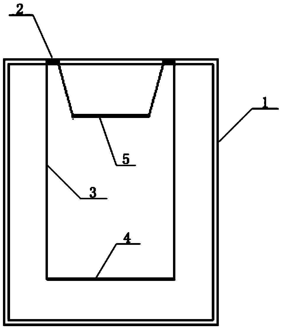
[0013] figure 1 The experimental device structure of the self-adaptive structure teaching provided by the embodiment of the present invention is shown. For ease of illustration, only the parts relevant to the present invention are shown.
[0014] The experimental device for adaptive structure teaching of the embodiment of the present invention, the experimental device for self-adaptive structure teaching includes: a frame, an outer frame, an inner frame, a rope, and a pulley;
[0015] The frame is set on the outermost side of the experimental device, the outer frame is set at the bottom of the frame, the inner frame is se...
PUM
 Abstract
Description
Claims
Application Information