Stator punching piece, stator core and motor

A technology for stator punching and stator iron core, which is applied in the fields of stator motor and stator punching, can solve the problems of difficult mold manufacturing, high mold production cost, easy fracture of bridge 43, etc., so as to reduce the magnetic leakage phenomenon, The mold is simple and the effect of ensuring reliability

Inactive Publication Date: 2013-12-18
GREE ELECTRIC APPLIANCES INC +4
View PDF4 Cites 10 Cited by
  • Summary
  • Abstract
  • Description
  • Claims
  • Application Information

AI Technical Summary

Problems solved by technology

However, since the bridge portion 43 has a relatively small length in the radial direction of the stator punching sheet 40, and is semicircular in shape and has a small radius of curvature, the bridge portion 43 is easily broken after stamping the stator punching sheet 40, and the die used for stamping the stator punching sheet 40 The design is complex and the manufacturing of the mold is difficult, resulting in high production costs of the mold
[0011] In addition, if the teeth of the stator core are completely laminated by the stator punches 40, there will be magnetic flux leakage in the stator core, which will affect the operation of the motor.

Method used


Image

  • Stator punching piece, stator core and motor
  • Stator punching piece, stator core and motor
  • Stator punching piece, stator core and motor

Examples


Embodiment Construction

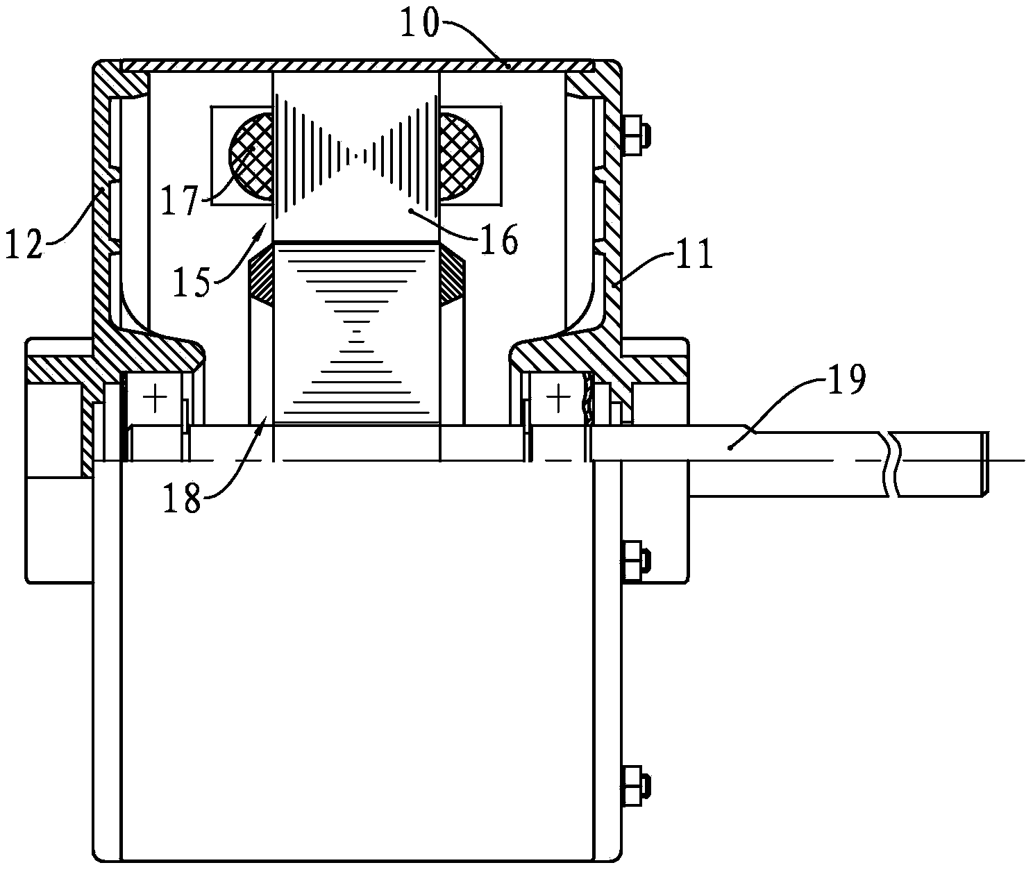
[0039] The motor of the present invention has a housing and end covers located on both sides of the housing. The housing and the end covers form a cavity. A stator and a rotor are installed in the cavity. A rotor mounting hole is provided in the middle of the stator. inside the hole. Moreover, the rotor shaft is installed in the middle of the rotor, and the rotor shaft can output power outward through the shaft hole.

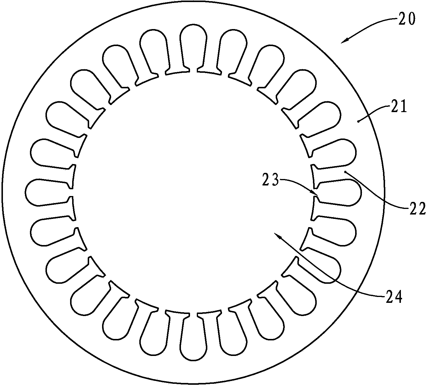
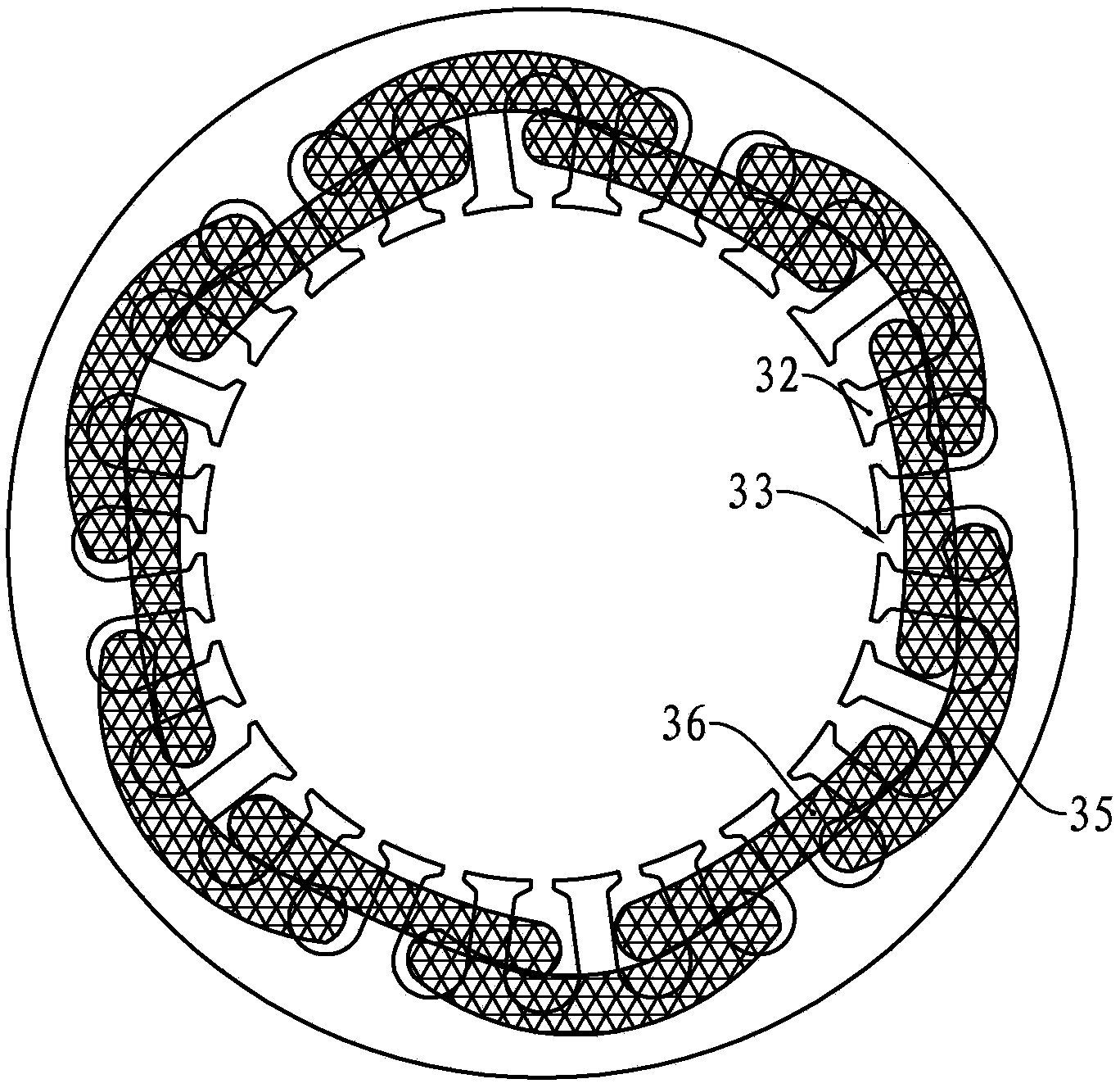
[0040] The stator of the present invention has a stator core. The stator core has a yoke and a tooth. The yoke is in the shape of an annular column. The tooth is located inside the yoke, and the tooth and the yoke are detachably connected.

[0041] see Image 6 and Figure 7, the tooth portion 50 of this embodiment has three first tooth portions, namely the first tooth portions 51 , 53 , 55 , and two second tooth portions, respectively the second tooth portions 52 , 54 . In the axial direction of the tooth portion 50, the first tooth portion and the second to...


PUM


Abstract

The invention provides a stator punching piece, a stator core and a motor. The stator punching piece is provided with an annular yoke part and a tooth part detachably connected with the yoke part. The tooth part is located in the yoke part, a plurality of teeth are circumferentially arranged on the tooth part, tooth roots of every two adjacent teeth are connected through a bridge part, every bridge part is provided with an inner arc close to the circle center of the tooth part and an outer arc far away from the circle center of the tooth part, inner arcs of a plurality of bridge parts are located on a first circumference, outer arcs of the plurality of bridge parts are located on a second circumference, and the first circumference and the second circumference are concentric circles with the circle center of the tooth part serving as the circle center. The stator core is provided with a first tooth part formed by stacking the stator punching pieces. The motor is provided with a stator and a rotor, and the stator comprises the stator core. Flux leakage of the stator core can be reduced, breakage of the stator punching piece from the bridge parts is avoided, and quality of the stator punching piece is improved.

Description

technical field [0001] The invention relates to the field of motors, in particular to a stator used by the motor, a stator punch for manufacturing the stator, and a motor with the stator. Background technique [0002] Motors are widely used in various electrical equipment in industrial production and life. The existing motors have a stator and a rotor. The rotor shaft is installed in the rotor and rotates with the rotation of the rotor, thereby outputting power. [0003] see figure 1 Some existing motors have a housing 10 and end covers 11 and 12 located at both ends of the housing 10. The housing 10 and the end covers 11 and 12 form a cavity in which a stator 15 and a rotor 18 are installed. The stator 15 It has a stator core 16 and a coil 17 wound on the stator core 16 . The rotor 18 is installed in the stator 15 and is rotatable relative to the stator 15 . The rotor shaft 19 is installed in the rotor 18 and has an interference fit with the rotor 18 . The rotor shaft 19...

Claims


Application Information

Patent Timeline
Patent Type & Authority Applications(China)
IPC IPC(8): H02K1/14
Inventor 邓家源陈川礼刘伟兵黄世杰
Owner GREE ELECTRIC APPLIANCES INC
Why Eureka
Try Eureka