Flow control device, flow control method, network flow management system, and network flow management method

A flow control device and network technology, applied in the direction of network flow/resource management, electrical components, wireless communication, etc., can solve problems such as inability to solve congestion, failure to consider user service characteristics, and inability to achieve communication, so as to reduce user congestion rate. , improve user experience, improve the effect of utilization

Inactive Publication Date: 2013-12-18
HITACHI LTD
View PDF6 Cites 23 Cited by
  • Summary
  • Abstract
  • Description
  • Claims
  • Application Information

AI Technical Summary

Problems solved by technology

However, this method only considers the use of a homogeneous network to switch users between adjacent cells to alleviate congestion. That is to say, in Patent Document 2, it does not consider the service characteristics requested by users, regardless of the service type. The same processing, sometimes even switching cells can not solve the congestion problem
Moreover, since handover is performed in different cells of the homogeneous network, if all the cells of the homogeneous network are in a congested state, even handover cannot achieve the purpose of communication

Method used


Image

  • Flow control device, flow control method, network flow management system, and network flow management method
  • Flow control device, flow control method, network flow management system, and network flow management method
  • Flow control device, flow control method, network flow management system, and network flow management method

Examples


no. 1 approach

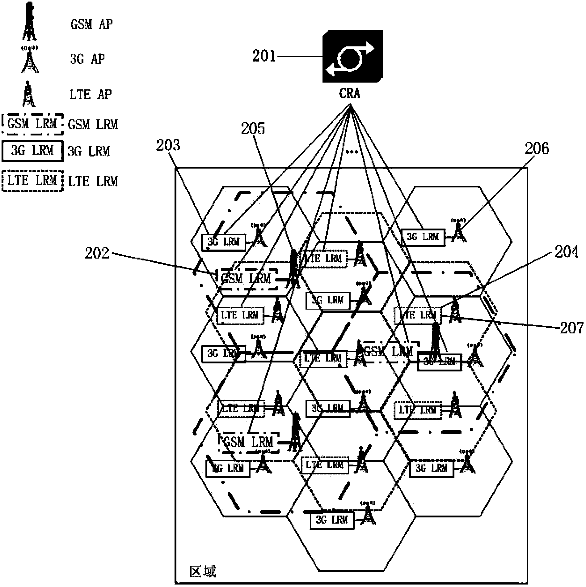
[0061] figure 1 It is a system configuration diagram showing the network traffic management system for single-area control according to the first embodiment of the present invention.

[0062] The network flow management system involved in the present invention is a system for managing the comprehensive flow of a "area" covered by multiple networks.

[0063] Among them, such as figure 1 As shown, a heterogeneous network composed of three cellular networks, namely GSM, 3G, and LTE, is exemplified in the managed area.

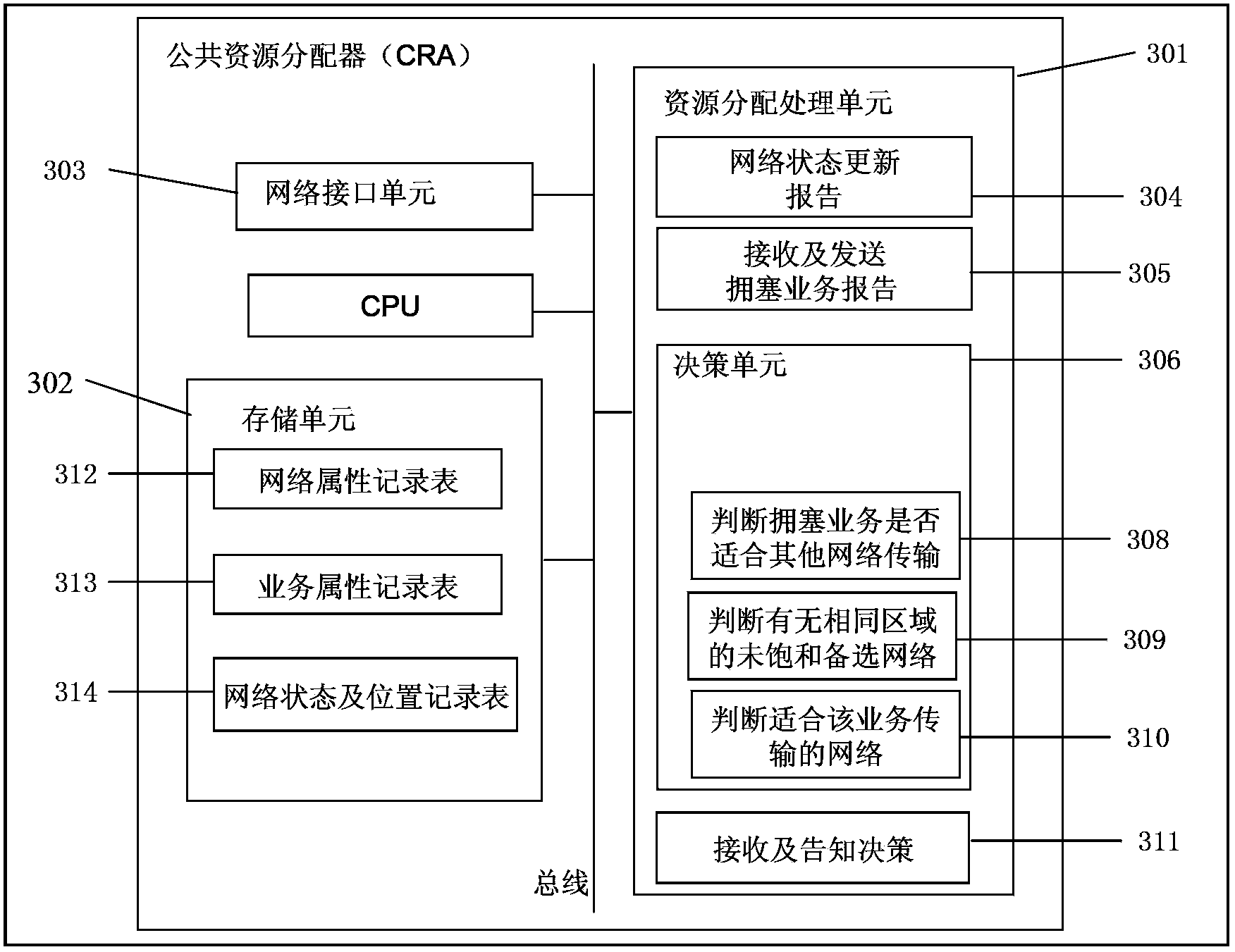
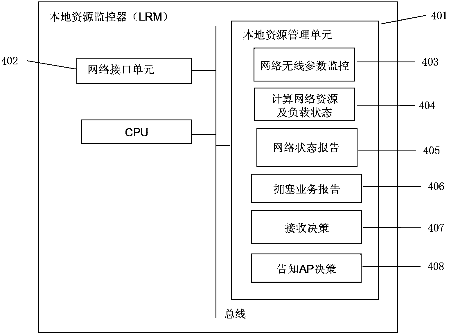
[0064] The network traffic management system such as figure 1 As shown, it includes: a common resource allocator (Common Resource Allocator: CRA) 201 that schedules and manages the resources of each network in the managed area, and a local resource monitor (Local Resource Monitor) that monitors local resources according to each network. : LRM) 202, 203, 204, and access points (ie: base stations) APs 205, 206, 207 of each network.

[0065] Among them, the publi...

no. 2 approach

[0113] In the above first embodiment, the embodiment in which the CRA 201 controls the traffic in a certain area covered by overlapping networks of multiple types has been described. However, when the area controlled by CRA201 is too large, the processing load of CRA201 will increase, and it may not even be able to handle switching between multiple networks. Therefore, multiple CRA201s can be considered to handle their own corresponding areas, and in the CRA201 The upper layer sets up a central traffic manager, through which the traffic of users on the border between different CRA201s or users on the edge of the area managed by the CRA201 is managed.

[0114] The difference between the second embodiment of the present invention and the first embodiment is that a central traffic manager (Central Traffic Manager: CTM) is provided. In the following description, the same reference numerals are given to the same parts as those of the first embodiment, and detailed descriptions are ...


PUM


Abstract

The invention provides a flow control device, a flow control method, a network flow management system and a network flow management method in order to effectively reduce user blocking rate and improve utilization of each network in a heterogeneous network. The flow control device comprises a receiving unit, a judging unit and a distributing unit, wherein the receiving unit receives network status information and network congestion information, the network status information comprises multiple network types between a base station and terminals and a service type requested by a user, the network congestion information shows whether the base station and the terminals congest or not, the judging unit judges whether the service type requested by the user is suitable for other network transmission in user's area or not under the condition that the network congestion information shows current network congestion of the service requested by the user, and from the other networks which are judged out by the judging unit and suitable for transmission, the distributing unit selects a certain network as an alternative target network to replace the current network.

Description

technical field [0001] The present invention relates to devices and methods for providing services in mobile communications. In particular, it relates to a flow control device and method for controlling flow when a heterogeneous network is used for communication transmission, and a network flow management system and method. Background technique [0002] In recent years, with the rapid development of information technology and intelligent terminals, a large number of applications have increased, resulting in a sharp increase in the amount of data transmitted in the communication network, and operators have continuously upgraded their networks to support high-speed data transmission. Among them, the key way to solve the increase in data transmission volume is still how to make better use of existing network resources and improve network transmission efficiency. Optimizing network resource allocation through network traffic and congestion control technology is one of the most ...

Claims


Application Information

Patent Timeline
Patent Type & Authority Applications(China)
IPC IPC(8): H04W28/10
Inventor 刘春光吉内英也
Owner HITACHI LTD
Why Eureka
Try Eureka