Printed circuit board

A printed circuit board and current path technology, applied in the direction of printed circuit components, etc., can solve the problem that the position of the power supply terminal and the load terminal cannot be adjusted smoothly

Inactive Publication Date: 2013-12-18
HONG FU JIN PRECISION IND (SHENZHEN) CO LTD +1
View PDF3 Cites 0 Cited by
  • Summary
  • Abstract
  • Description
  • Claims
  • Application Information

AI Technical Summary

Problems solved by technology

However, when the wiring between the power supply terminal and the load terminal is dense, the position between the power supply terminal and the load terminal cannot be adjusted smoothly

Method used


Image

  • Printed circuit board
  • Printed circuit board

Examples


Embodiment Construction

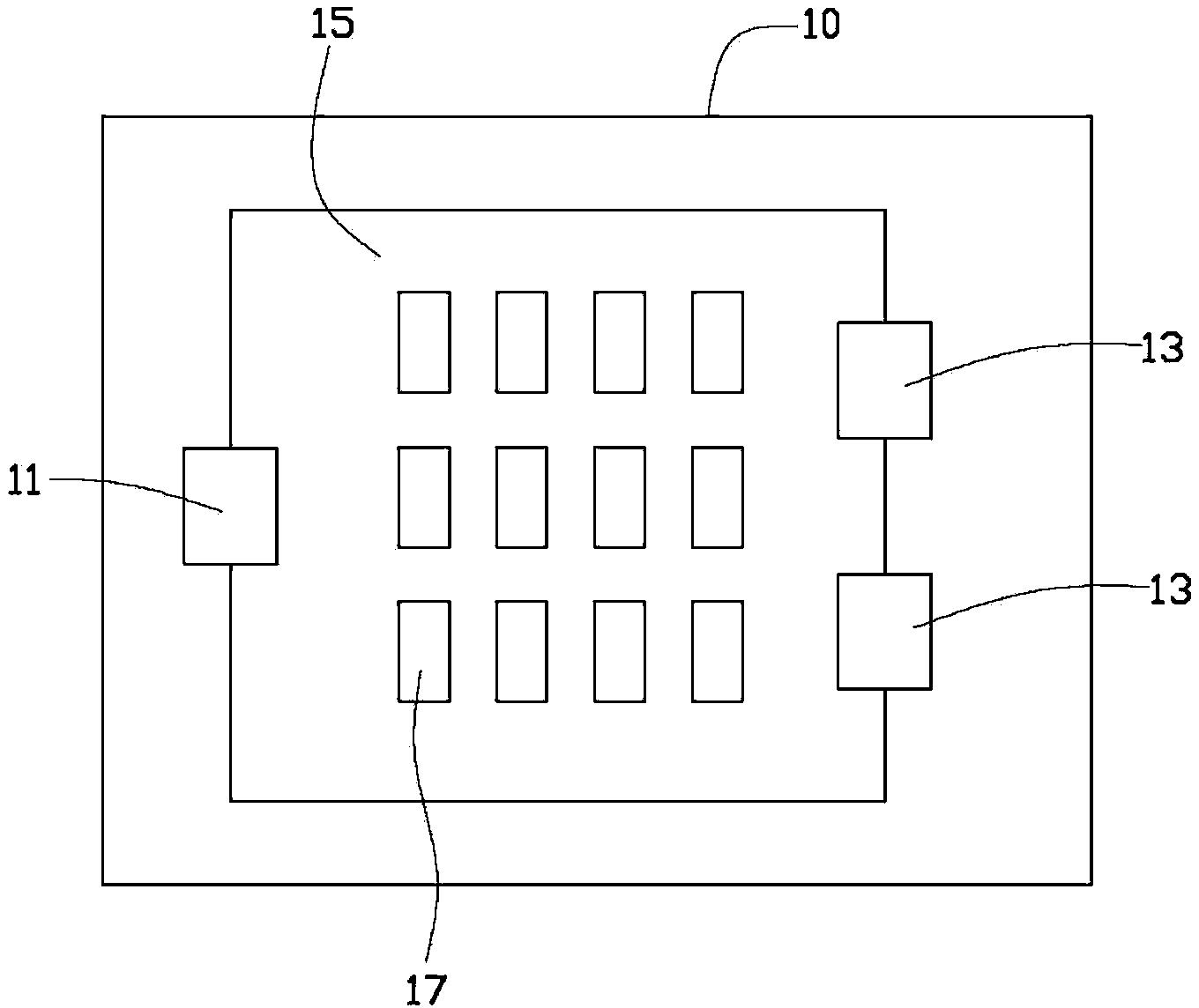
[0011] see figure 1 , the printed circuit board 10 of the preferred embodiment of the present invention includes a power supply 11 , a load 13 , a copper foil 15 and a metal foil 17 . The power supply 11 , the load 13 and the copper foil 15 are electrically connected in sequence, and the current output by the power supply 11 flows to the load 13 through the copper foil 15 .

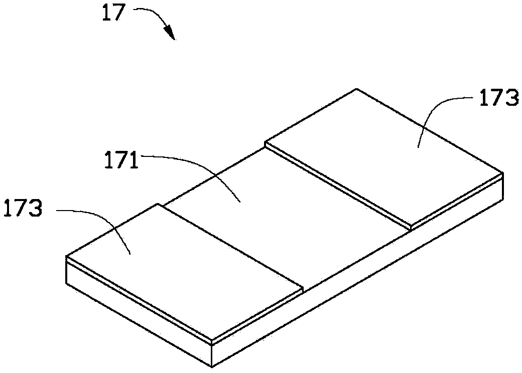
[0012] Please also refer to figure 2 , the metal foil 17 is welded on the copper foil 15 by surface mount technology (Surface Mount Technology, SMT). Specifically, the metal foil 17 includes a soldering surface 171 . Soldering pads 173 are provided on the soldering surface 171 . In this preferred embodiment, there are two welding pads 173 , which are respectively arranged at opposite ends of the welding surface 171 . The surface of the metal foil 17 except the pad 173 is covered with insulating varnish. The metal foil 17 is welded on the copper foil 15 through the pad 173. In this way, the metal foi...


PUM


Abstract

A printed circuit board comprises a power source, copper foil, a load and a metal foil sheet, wherein the power source, the copper foil, the load and the metal foil sheet are sequentially and electrically connected. The metal foil sheet is welded to the copper foil. According to the printed circuit board, the metal foil sheet is welded to the copper foil, so that the metal foil sheet and the copper foil are connected in parallel, the general series impedance between the power source and the load is reduced, therefore, the current flowing through the copper foil is increased, and the influence, caused by the equivalent impedance of the copper foil, on the transmission efficiency of an output current of the power source is effectively reduced.

Description

technical field [0001] The invention relates to a printed circuit board, in particular to a printed circuit board which can increase the current flowing on the copper foil. Background technique [0002] Copper foils with a larger area are generally used on printed circuit boards to transmit high-current signals. Since the copper foil has an equivalent impedance, that is, there is a series impedance between the power supply terminal and the load terminal, after the current output from the power supply terminal reaches the load terminal through the copper foil, the current transmission efficiency will be reduced. The current solution is generally to adjust the position between the power supply terminal and the load terminal to reduce the distance between the power supply terminal and the load terminal to improve the current transmission efficiency. However, when the traces between the power supply terminal and the load terminal are dense, the position between the power supply...

Claims


Application Information

Patent Timeline
Patent Type & Authority Applications(China)
IPC IPC(8): H05K1/02
Inventor 叶家铭田钧元吴至紘
Owner HONG FU JIN PRECISION IND (SHENZHEN) CO LTD
Why Eureka
Try Eureka