
Self-oscillation power amplifier

A technology of power amplifier and self-oscillation, applied in the direction of power amplifier, amplifier, improved amplifier to improve efficiency, etc.

Inactive Publication Date: 2006-12-06
ALCATEL LUCENT SAS
View PDF1 Cites 0 Cited by
  • Summary
  • Abstract
  • Description
  • Claims
  • Application Information

AI Technical Summary

Problems solved by technology

[0004] The object of the present invention is therefore to provide a power amplifier device of the above-mentioned known type, but which solves the above-mentioned problems of efficiency, supply modulation and noise, while still being very simple

Method used


Image

  • Self-oscillation power amplifier
  • Self-oscillation power amplifier
  • Self-oscillation power amplifier

Examples


Embodiment Construction

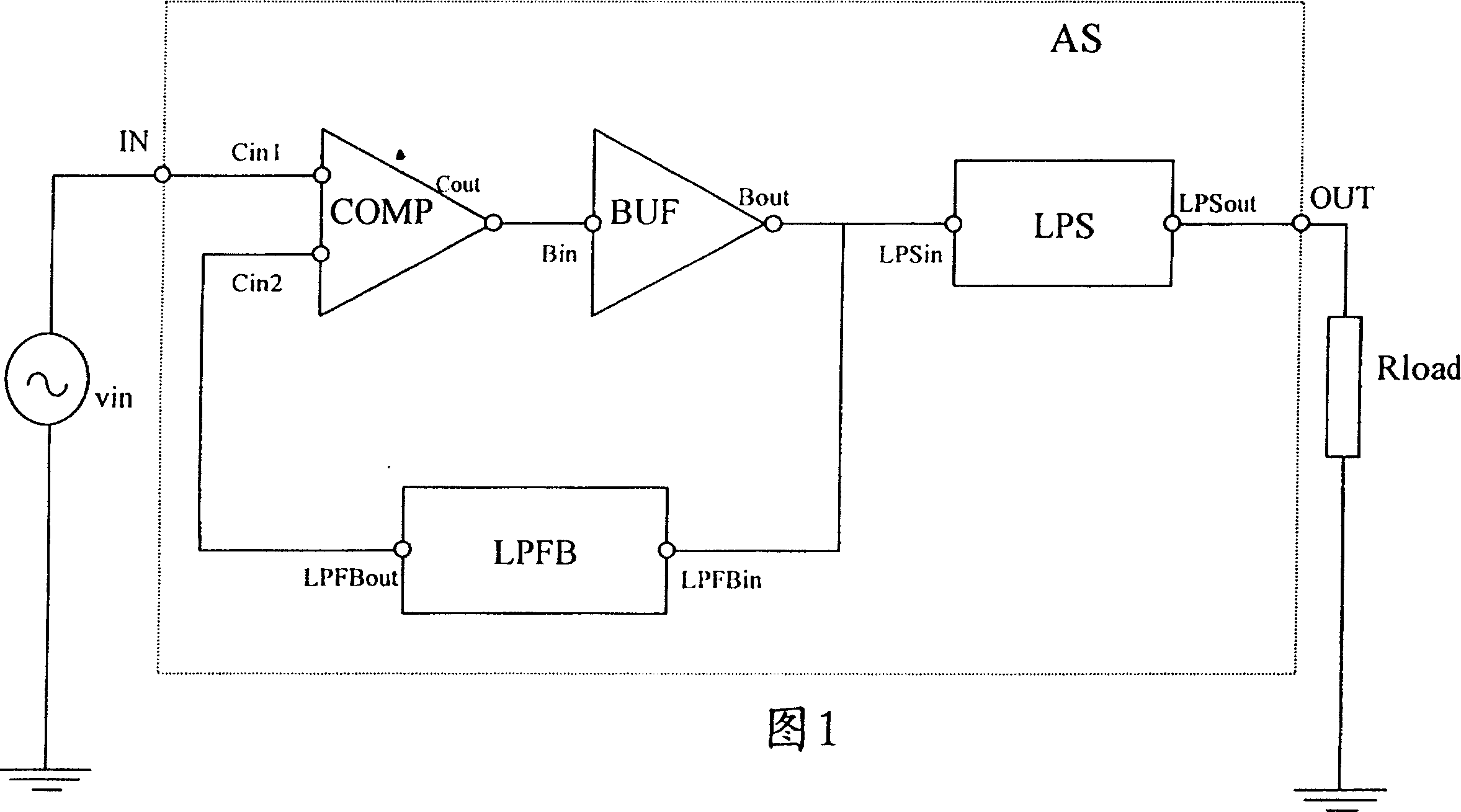
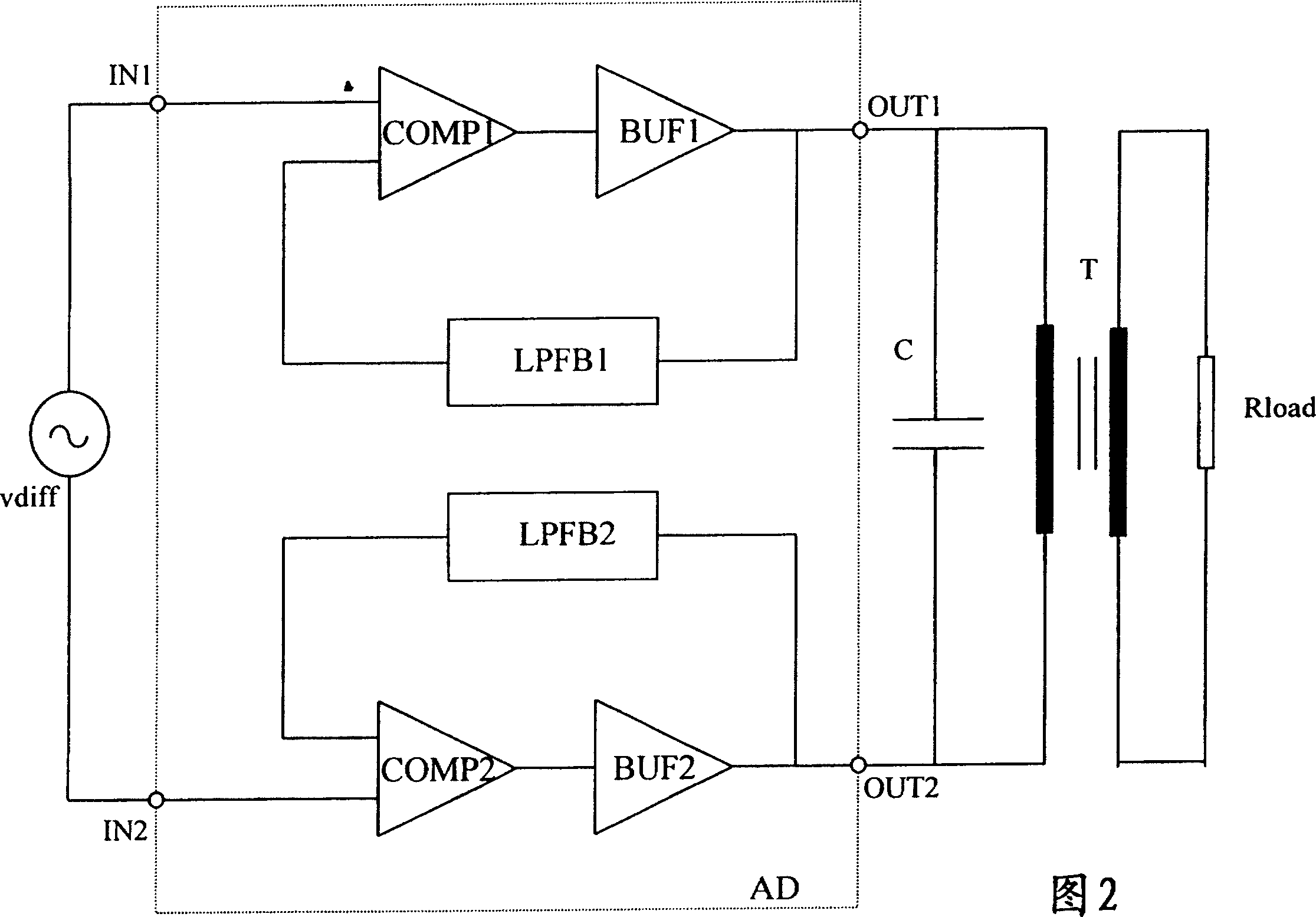
[0022] The present invention relates to a differential amplifier device AD ​​as shown in FIG. 2, wherein each of the two differential components can be represented by the circuit of FIG. 1. The basic operation of the differential embodiment will be discussed by studying the single-ended circuit of FIG. 1. The specific advantages of the differential embodiment of FIG. 2 will be further described in later paragraphs.

[0023] The amplifier device of FIG. 1 includes an input terminal IN to which an input signal vin can be provided. The input terminal IN is coupled to the first input terminal Cin1 of the comparator COMP. The comparator has a second input terminal Cin2 and is further adapted to compare the input signals provided to the two input terminals with each other. The comparison result is sent to the output terminal Cout of the comparator, and the output terminal Cout is further coupled to the input terminal Bin of the digital buffer BUF. The latter amplifies the digital input ...


PUM


Abstract

A power amplifier includes a comparator (COMP) to which an input signal is applied, a digital buffer (BUF) coupled via a feedback low-pass filter (LPFB) to a second input terminal (Cin2) of said comparator (COMP). An unstable loop is thereby created with an oscillation frequency related to the bandwidth of the feedback low-pass filter. In the presence of an input signal this self-oscillation frequency linearizes the system resulting in a power amplifier with excellent power efficiency. In a differential version two of these self-oscillating loops are provided . The coupling of the two loops thereby withhelds the high-frequency self-oscillation from the load.

Description

Technical field [0001] The invention relates to a power amplifier. Background technique [0002] Such power amplifiers are well known in the art, for example, from the international PCT application with the international publication number WO98 / 19391. In its Fig. 7 a power amplifier including a self-oscillating loop is disclosed. The self-oscillating loop includes a modulator / switching stage Kp, and the output of the modulator / switching stage Kp is coupled back to the modulator / switching stage. The details of the modulator stage are further disclosed in Figure 10 of this prior art document. [0003] The disadvantage of this prior art amplifier circuit is that it has a power spectrum peak near the self-oscillation frequency, which degrades the power efficiency of the xDSL system. In addition, these prior art solutions will also cause xDSL noise and power modulation problems. In addition, the prior art circuit is still very complicated due to the existence of several filters. Espec...

Claims


Application Information

Patent Timeline
Patent Type & Authority Patents(China)
IPC IPC(8): H03F3/21H03F3/217H03F1/00H03F3/20H03F1/02
CPCH03F3/2173H03F2200/537H03F1/0205H03F3/45179H03F2200/541
Inventor 蒂姆·皮森斯米歇尔·斯特伊尔特
Owner ALCATEL LUCENT SAS
Learn More