Scroll compressor

A scroll compressor and movable scroll technology, which is applied in the direction of rotary piston machinery, rotary piston pumps, mechanical equipment, etc., can solve the problems of difficult processing and high processing precision requirements for spiral passages, and achieve improved reliability, Effect of suppressing wear and improving durability

Inactive Publication Date: 2013-12-18
SANYO ELECTRIC CO LTD
View PDF9 Cites 10 Cited by
  • Summary
  • Abstract
  • Description
  • Claims
  • Application Information

AI Technical Summary

Problems solved by technology

[0004] However, in such a flow rate limiting member, the allowable flow rate depends on the size of the helical passage formed on the outer periphery of the main body, so the machining accuracy of the helical passage is required to be high, and there is a problem that processing becomes difficult.

Method used


Image

  • Scroll compressor
  • Scroll compressor
  • Scroll compressor

Examples


Embodiment Construction

[0054] Hereinafter, embodiments of the present invention will be described in detail with reference to the drawings.

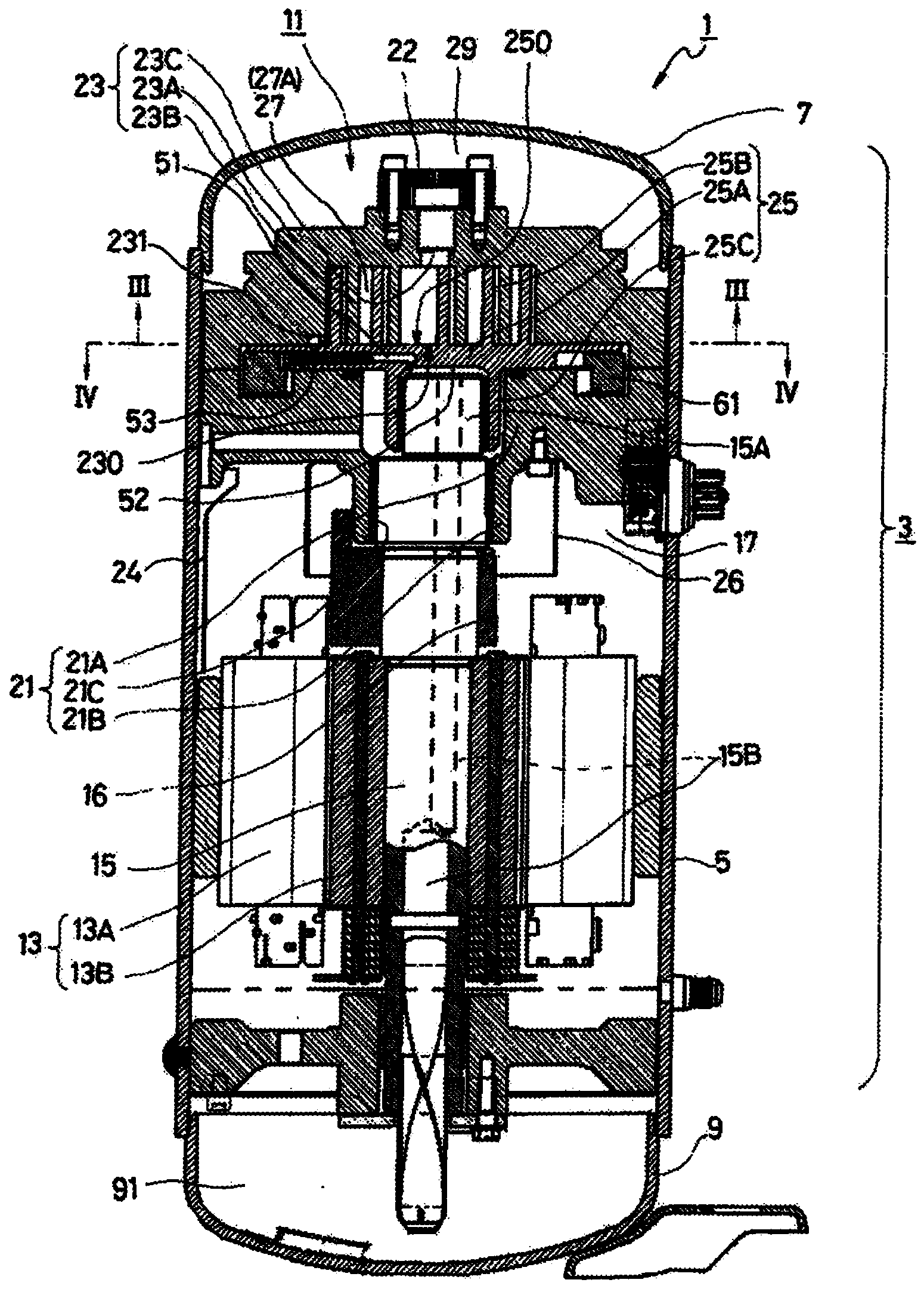
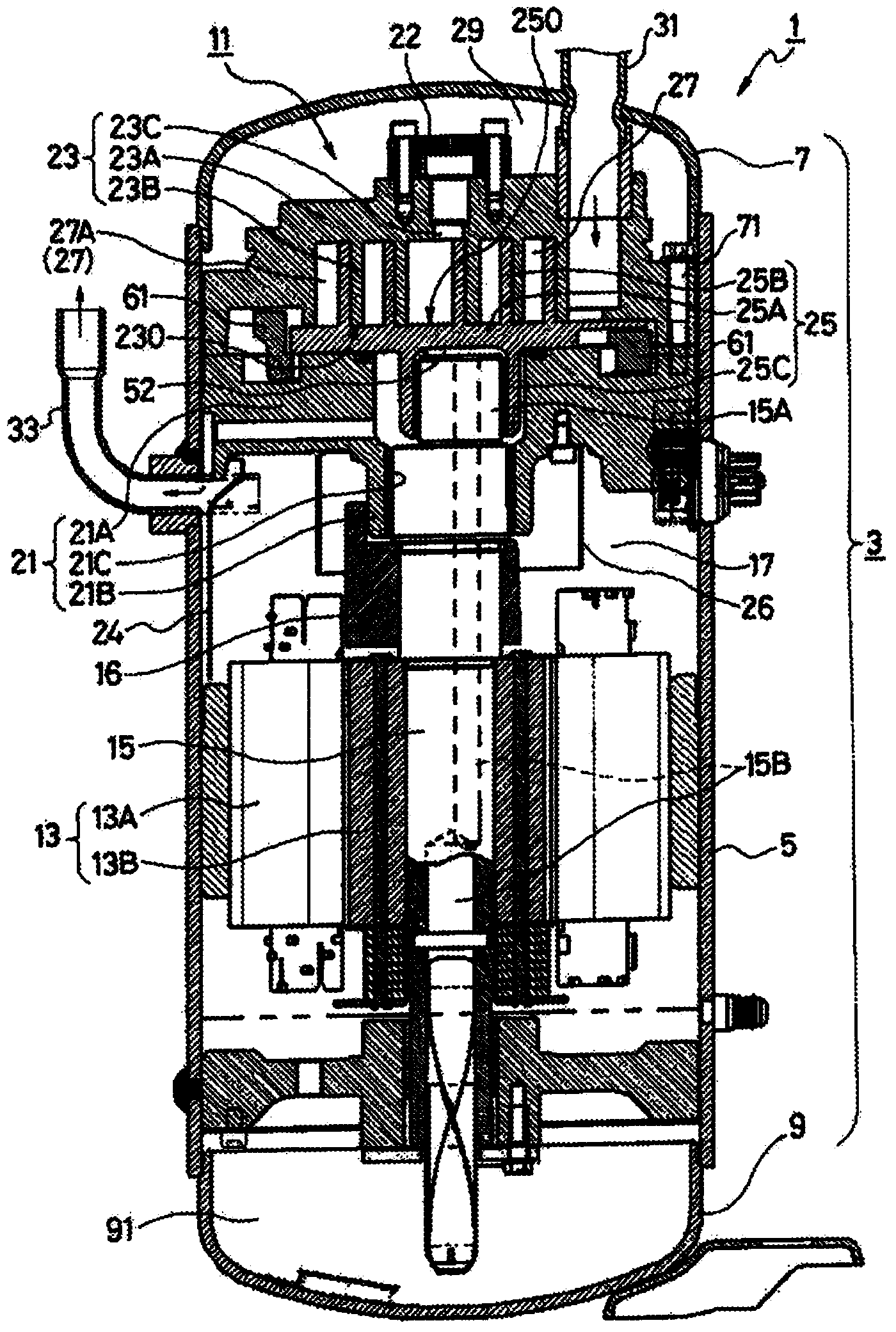
[0055] figure 1 It is a diagram showing an internal high-pressure scroll compressor 1 according to an embodiment of the present invention. The compressor 1 is connected to a refrigerant circuit not shown in the figure that circulates a refrigerant and performs refrigeration cycle operation, and is controlled by an inverter. to compress the refrigerant.

[0056] The compressor 1 has a vertically long cylindrical sealed dome-shaped casing 3 . The casing 3 is a pressure vessel composed of a casing main body 5, a bowl-shaped upper cover 7 and a bowl-shaped lower cover 9. The inside of the casing 3 becomes a cavity, and the casing main body 5 has a The cylindrical main body portion of the axis; the bowl-shaped upper cover 7 is airtightly welded and integrally joined to the upper end of the casing main body 5, and has an upwardly protruding convex surface; the bo...


PUM


Abstract

[Problem] To provide a scroll compressor capable of supplying more oil to secure the minimum oil supply quantity necessary even during low-speed rotation. [Solution] A scroll compressor includes: a communication passage (51) formed in a moving scroll (25), which discharges oil from a high-pressure portion in a casing to a space between panels of a fixed scroll (23) and the moving scroll (25); and a communication hole (53) formed in the communication passage (51) of the panel section of the moving scroll (25), the communication hole (53) approaching the vicinity of the entrance of a low-pressure portion (27A) of a compression chamber surrounded by wraps of both the fixed scroll (23) and the moving scroll (25), and extending to and opening at the panel surface. A narrow oil groove is formed in the fixed scroll (23) and supplies oil to the compression chamber. In the panel of the fixed scroll (23) approaching the wall surface portion of the moving scroll (25), an oil receiving hole (231) is formed in the oil groove, with the oil receiving hole (231) constantly overlapping and communicating with the communication hole (53) as the moving scroll (25) revolves so as to orbit on the top surface of the fixed scroll (23).

Description

technical field [0001] The present invention relates to a scroll compressor, and more particularly, to a scroll compressor capable of preventing insufficient lubricating oil occurring at a low rotational speed in an inverter type or the like. Background technique [0002] Conventionally, as an example of a compressor that compresses a refrigerant in a refrigeration cycle, for example, a scroll compressor is known. A scroll compressor is provided with a compression mechanism in a casing, and the compression mechanism has a fixed scroll and a movable scroll on which scroll-shaped wraps meshing with each other protrude. The fixed scroll is fixed on the casing, and the movable scroll is connected to the eccentric shaft portion of the drive shaft. Furthermore, the movable scroll only orbits with respect to the fixed scroll without rotating, thereby reducing the volume of the compression chamber formed between both scrolls and compressing the refrigerant therein. [0003] In add...

Claims


Application Information

Patent Timeline
Patent Type & Authority Applications(China)
IPC IPC(8): F04C18/02
CPCF04C18/0215F04C18/0253F04C23/008F04C29/025F04C29/028
Inventor 林哲广饭塚敏昆努阿久泽克城相田健二清川保则杉本和禧
Owner SANYO ELECTRIC CO LTD
Why Eureka
Try Eureka