Compressor

A compressor and compression mechanism technology, applied in the field of compressors, can solve problems such as poor lubrication and reduction of sliding parts

Active Publication Date: 2021-12-10
MITSUBISHI ELECTRIC CORP
View PDF9 Cites 0 Cited by
  • Summary
  • Abstract
  • Description
  • Claims
  • Application Information

AI Technical Summary

Problems solved by technology

However, the amount of oil supplied during high differential pressure and low-speed operation is reduced compared with the amount of oil suppl

Method used


Image

  • Compressor
  • Compressor
  • Compressor

Examples


Embodiment approach 1

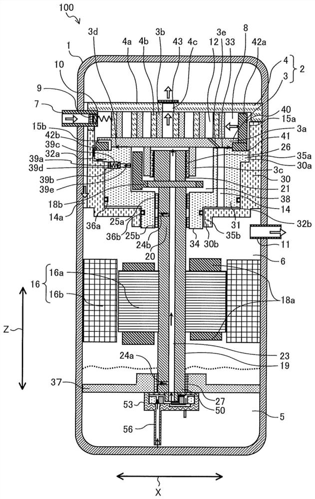
[0018] figure 1 It is a schematic longitudinal sectional view showing the compressor according to the first embodiment. As follows, while referring to figure 1 , one Next, the configuration of the compressor 100 will be described. figure 1 The compressor 100 is a so-called vertical scroll compressor, and compresses and discharges a working gas such as refrigerant, for example. The compressor 100 includes an airtight container 1 , a compression mechanism 2 , a motor 16 , and a drive shaft 19 . exist figure 2 The solid arrows in the middle airtight container 1 represent the flow of oil, and the hollow arrows represent the flow of working gas.

[0019] The airtight container 1 is formed in a cylindrical shape, for example, and has pressure resistance. A suction pipe 7 for introducing working gas into the airtight container 1 is connected to one side of the airtight container 1 , and a discharge pipe 11 for releasing compressed working gas from the airtight container 1 to ...


PUM


Abstract

A compressor comprises a sealed container having: an oil accumulation space that accumulates oil; a compression mechanism portion that is accommodated in the sealed container and that compresses a working gas flowing into the sealed container; and a drive shaft that drives the compression mechanism portion, the drive shaft having an oil supply flow channel formed therein. The compressor also comprises an oil supply pump that is driven by the rotation of the drive shaft and that supplies the oil accumulated in the oil accumulation space to the oil supply flow channel of the drive shaft, and a bearing to which the oil is supplied from the oil supply flow channel and which supports the rotation of the drive shaft. A gap between the bearing and the drive shaft serves as a bearing flow channel through which the oil flows, the gap being set such that, within the oil flow channel in the oil supply pump, the flow channel resistance of a part of a clearance flow channel is less than the flow channel resistance of the bearing flow channel.

Description

technical field [0001] The present invention relates to a compressor used in, for example, a refrigeration device or an air conditioner. Background technique [0002] Conventionally, there is known a compressor as shown in Patent Document 1. This compressor is provided with: an airtight container accumulating oil at the bottom, an electric motor generating rotational force in the airtight container, a drive shaft with an oil supply passage inside, and a drive shaft through the drive shaft. The compression mechanism unit that compresses the fluid by the rotation of the fluid is supplied with oil by the differential pressure between the bottom of the airtight container and the compression mechanism unit (for example, refer to Patent Document 1). [0003] In addition, as a compressor using another oil supply method, there is a compressor including a displacement type oil supply pump at the lower end of a drive shaft (for example, refer to Patent Document 2). In Patent Document...

Claims


Application Information

Patent Timeline
IPC IPC(8): F04C29/02F04C18/02
CPCF04C29/02F04C18/02
Inventor 权守真人
Owner MITSUBISHI ELECTRIC CORP
Why Eureka
Try Eureka