The driving structure of the connecting rod of the beverage extraction device

An extraction device and connecting rod drive technology are applied in the field of drive structures for driving movable parts in beverage extraction devices to move back and forth, which can solve the problems of long piston movement stroke, low work efficiency, and long total movement path, and achieve the purpose of driving parts. The effect of moving forward, fast moving parts forward, and improving work efficiency

Active Publication Date: 2016-03-09
NINGBO QUANJING ELECTRIC TECH
View PDF8 Cites 0 Cited by
  • Summary
  • Abstract
  • Description
  • Claims
  • Application Information

AI Technical Summary

Problems solved by technology

[0007] The mode of relative movement of the two parts in the existing beverage preparation device regardless of the driving mode is that one part is fixed relative to the machine base, the other part slides relative to the machine base, and the mobile part slides to the extraction state. The total moving path is very long, because the pusher that drives the movable part is directly fixed at the rear of the movable part, the driving structure directly drives the part or the pusher to slide, and the movable pusher is in the hydraulic drive structure. Therefore, the distance to move the piston is the same as the distance to move when the movable part is closed, resulting in a long stroke of the piston, which will inevitably prolong the time required for the beverage extraction device (such as a coffee machine) to prepare a beverage (such as coffee). Waiting time, low work efficiency

Method used


Image

  • The driving structure of the connecting rod of the beverage extraction device
  • The driving structure of the connecting rod of the beverage extraction device
  • The driving structure of the connecting rod of the beverage extraction device

Examples


Embodiment Construction

[0034] The present invention will be further described in detail below in conjunction with the accompanying drawings and embodiments.

[0035] Such as Figure 1-13 Shown is a preferred embodiment of the present invention.

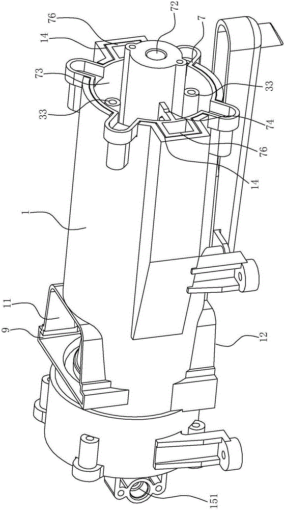
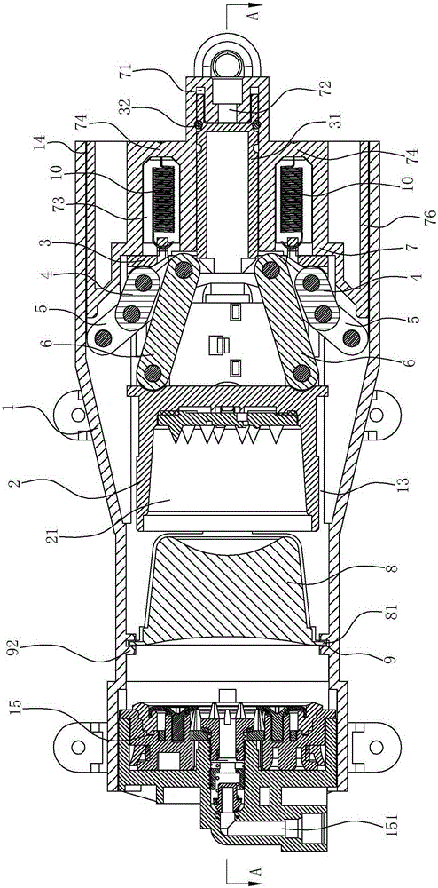
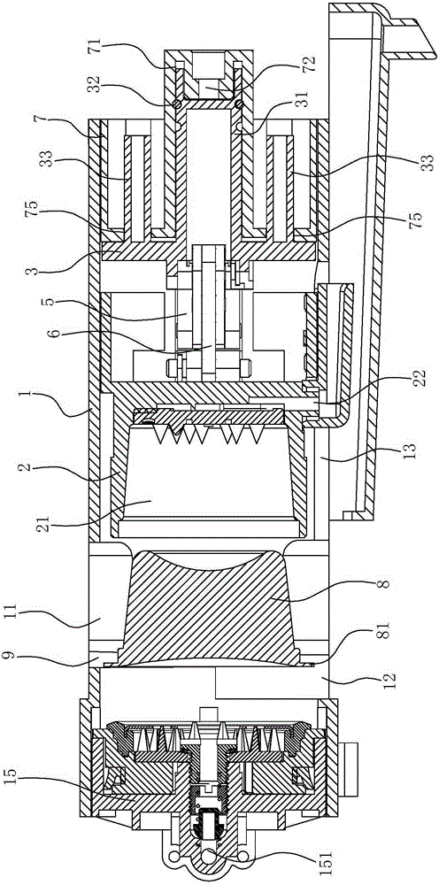
[0036] A driving structure of a machine link for a beverage extracting device, comprising a machine base 1 with a packing opening 11 and a bag dropping opening 12, and a machine part 2 constrained in the machine base that can slide back and forth. In this embodiment, the machine part 2 The front part of the machine base has an accommodating cavity 21 for accommodating the beverage pack 8, and a beverage outlet channel 22 communicating with the accommodating cavity 21. As a complete extraction system, the front end of the base 1 is fixed with a fixed part 15, and the fixed part 15 There is a hot water channel 151 for hot water to pass through, and the extraction chamber for accommodating the beverage bag 8 can be formed after the mechanism 2 and the fixed mec...


PUM


Abstract

The invention relates to an element link drive structure of a drink extraction unit. The element link drive structure comprises a base and an element and is characterized in that a moving member capable of sliding back and forth is restrained inside the base, the moving member is disposed at the rear of the element, the moving member is connected with the rear of the element through two bilaterally symmetric link structures, each link structure comprises a first link, a second link and a third link, one end of the first link is rotatably connected to one side of the moving member, one end of the second link is rotatably connected to one side of the base, the other end of the first link is rotatably connected to the middle of the second link, the other end of the second link is rotatably connected with one end of the third link, and the other end of the third link is rotatably connected with one side of the rear of the element. Forward movement distance of the element can be amplified by the link structures through the forward movement distance of the moving member in the drive structure, namely the element can move forward at a large distance only by driving the moving member to move forward at a small distance, and accordingly the element is driven to move forward quickly and work efficiency is improved greatly.

Description

technical field [0001] The present invention relates to a beverage extracting device, in particular to a driving structure for driving movable parts in the beverage extracting device to move back and forth. The beverage extracting device may be a coffee machine or other similar equipment. Background technique [0002] A coffee machine is a machine for preparing coffee beverages. The traditional components of a coffee machine include a water tank, a heating element, and a water pump. When in use, the capsule containing the coffee powder is placed in the coffee machine. When in use, the driving structure is used to Close the two parts in the coffee machine to form an extraction cavity. At this time, the coffee capsule is located in the extraction cavity. When extracting, the heated water is pumped into the extraction cavity. The water flows through the coffee raw materials to be extracted, and the coffee beverage is extracted from the coffee The outlet pipe of the machine flow...

Claims


Application Information

Patent Timeline
Patent Type & Authority Patents(China)
IPC IPC(8): A47J31/44
Inventor 景昱东谢长军
Owner NINGBO QUANJING ELECTRIC TECH
Why Eureka
Try Eureka