Brake unit for automatic profile stamping and shearing machines

A brake device and automatic flushing technology, applied in the field of brake devices, can solve the problems of high cost, inconvenient adjustment, poor reliability, etc.

Inactive Publication Date: 2013-12-25
ANQING YANGGUANG MACHINERY MFG
View PDF6 Cites 5 Cited by
  • Summary
  • Abstract
  • Description
  • Claims
  • Application Information

AI Technical Summary

Problems solved by technology

However, most of the punching and shearing machines on the market do not have a brake device. If the punching speed needs to be reduced, the power can only be turne

Method used


Image

  • Brake unit for automatic profile stamping and shearing machines
  • Brake unit for automatic profile stamping and shearing machines

Examples


Embodiment Construction

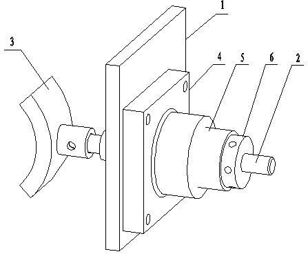
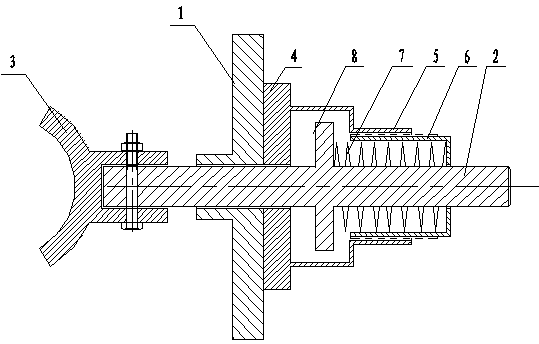
[0008] The brake device of an automatic profile punching and shearing machine of the present invention will be described in further detail below with reference to the accompanying drawings.

[0009] by figure 1 , figure 2 It can be seen that the brake device of the automatic profile punching and shearing machine of this embodiment is composed of frame 1, brake shaft 2, brake pad 3, fixed block 4, brake sleeve 5, tightening nut 6 and spring 7; 2 Installed in the hole in the middle of the frame 1, a brake pad 3 is fixed at the left end of the brake shaft 2. The brake sleeve 5 and the tightening nut 6 are respectively sleeved on the brake shaft 2, and the brake sleeve 5 is connected to the The frame 1 is fixed, the fixing block 4 is fixedly connected with the frame 1 by screws, the tightening nut 6 is arranged on the right side of the brake sleeve 5, the inner wall of the right end of the brake sleeve 5 is provided with threads, and the tightening nut 6 is provided on the outer wal...


PUM


Abstract

The invention discloses a brake unit for automatic profile stamping and shearing machines. The brake unit comprises a support, a brake shaft, a brake pad, a fixed block, a brake shaft sleeve, a retaining nut and a spring; the brake shaft is mounted in the central hole of the support, the brake pad is fixed on the left end of the brake shaft, the brake shaft sleeve and the retaining nut are respectively sleeved on the brake shaft, the brake shaft sleeve is fixed on the support through the fixed block, the outer wall of the retaining nut is screwed in the inner wall of the brake shaft sleeve, the brake shaft is provided with the spring and a lug boss, and the spring is arranged between the lug boss and the right wall of the retaining nut. Adopting the technical scheme of the invention, the brake unit has the advantages of simple structure, reasonable design, good braking effect, safety and reliability, can conveniently adjust stamping speed, and is convenient to mount and maintain.

Description

Technical field [0001] The invention belongs to the field of mechanical equipment, and specifically relates to a brake device of an automatic profile punching and shearing machine. Background technique [0002] In the machinery manufacturing industry, people often need to use a punching and shearing machine to cut the parts to be processed into products that meet the length requirements. Profiles in the market are usually long strips, which need to be divided and cut. The work on the profiles is mainly completed by the punching die on the punching machine. The front end of the profile is inserted into the workpiece positioning slot of the lower die of the punching die for positioning, and then The upper mold of the mold is moved downward by the punch, and the punch is inserted into the lower mold to cut the profile. However, most of the punching and shearing machines currently on the market do not have a brake device. If the punching speed needs to be reduced, it can only be con...

Claims


Application Information

Patent Timeline
IPC IPC(8): B21D28/02F16D49/00F16D65/18F16D121/14
Inventor 阮魁林
Owner ANQING YANGGUANG MACHINERY MFG
Why Eureka
Try Eureka