Stamping tool

A stamping die and punching column technology, which is applied in the field of molds, can solve the problems of time-consuming, increasing the stroke of the punch, and injuring human hands, so as to eliminate potential safety hazards, speed up stamping speed, and improve work efficiency.

Inactive Publication Date: 2013-12-25
泰州市凌峰机电设备有限公司
View PDF6 Cites 5 Cited by
  • Summary
  • Abstract
  • Description
  • Claims
  • Application Information

AI Technical Summary

Problems solved by technology

[0003] The stamping dies of the prior art have the following defects: each time a screw is punched, five steps of mold opening, loading, stamping mold clamping, mold opening, and demoulding need to be carried out separately, and as many screws as needed to be stamped need to be repeated as many times as necessary. The speed is slow and the efficiency is low, and continuous stamping and forming cannot be performed; secondly, because the round bar is placed between the upper mold and the lower mold when discharging, in this way, if the mold opening range is too small before discharging and when the mold is opened, two The distance between the molds is not enough, it is difficult for people to put the round rod in, but if the mold opening range is too large, the stroke of the punch will be increased when the mold is opened and closed, which will consume more time and further reduce the efficiency. There is a certain danger in discharging the material between the two molds. If the punch is accidentally activated, it may hurt the hands; moreover, because the opening of the lower mold is facing upwards, the demoulding process is too inconvenient

Method used


Image

  • Stamping tool
  • Stamping tool
  • Stamping tool

Examples


Embodiment Construction

[0017] The present invention will be further described below in conjunction with the accompanying drawings and specific embodiments.

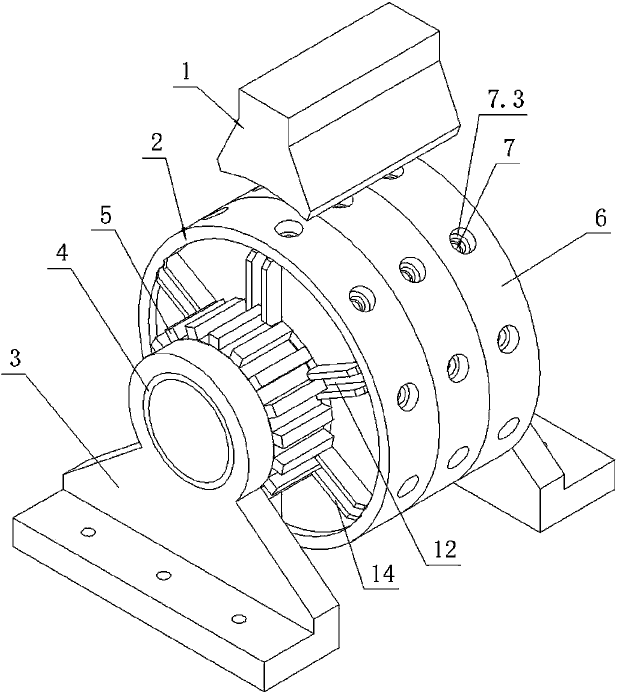
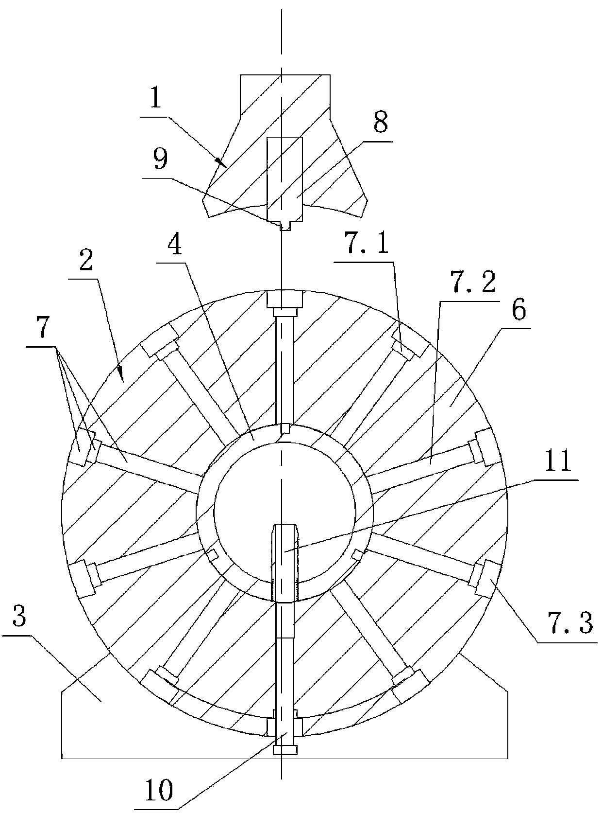
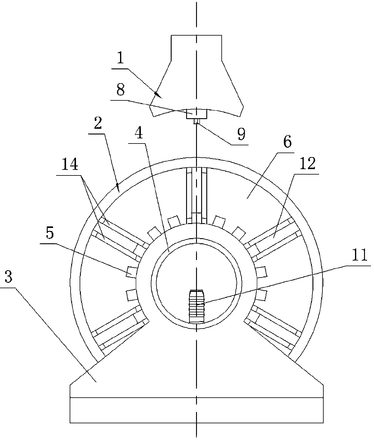
[0018] like figure 1 , figure 2 , image 3 , Figure 4 As shown, the stamping die of the present invention includes a punch 1 and a die shell 2. The punch 1 is fixed with a conventional punching drive such as an air cylinder. The formwork 2 includes two supports 3 , a rotating shaft 4 , a transmission gear 5 driven by an electric motor and three rotating disks 6 . Transmission gear 5 meshes with the output gear of the output shaft of the motor or is meshed with the output gear through a belt for transmission. Both ends of the rotating shaft 4 are respectively fixed to the two supports 3 . The transmission gear 5 and all three rotating disks 6 can be rotatably fitted on the rotating shaft 4 . Specifically, both the rotating disk 6 and the transmission gear 5 are provided with a central hole, and the rotating disk 6 and the transmission g...


PUM


Abstract

The invention discloses a stamping tool comprising a punch (1) and a die shell (2). The die shell (2) comprises two supports (3), a rotary shaft (4), a transmission gear and at least two rotary plates (6). Two ends of the rotary shaft (4) are fixed to the two supports (3) respectively. The transmission gear and all rotary plates (6) are rotatably fitted to the rotary shaft (4) in a sleeving manner. The outer peripheral surface of the each rotary plate (6) is provided with a plurality of radial through holes (7). The punch (1) is provided with at least two stamping posts (8) as many as the rotary plates (6). The stamping posts (8) are arranged in a row and right face a highest row of radial through holes (7) in the rotary plates (6). The rotary shaft (4) is further connected with a nozzle (11). The stamping tool is high in stamping speed, efficient, safe, and handy.

Description

technical field [0001] The invention relates to the technical field of molds, in particular to a stamping mold for stamping screws. Background technique [0002] The stamping die of the traditional stamping screw includes a lower die and an upper die. The upper end of the lower die is provided with a blind hole that matches the shape of the screw, that is, the lower die cavity. The lower end of the upper die is provided with cylindrical pits. The top is provided with hexagonal prism protrusions, and the cavity between the cylindrical recess and the hexagonal prism protrusions constitutes an upper die cavity that matches the shape of the head of the hexagon socket head screw, and the centerlines of the upper and lower die cavities coincide. Fix the lower mold, and put a round rod into the lower mold cavity. The length of the round rod is greater than the height of the lower mold cavity, and the upper mold and the punch are fixed. Drive the punch to make the two molds close to...

Claims


Application Information

Patent Timeline
Patent Type & Authority Applications(China)
IPC IPC(8): B21D53/24B21D37/10
Inventor 陆昱森
Owner 泰州市凌峰机电设备有限公司
Why Eureka
Try Eureka