Machine tool for machining long bars

A machine tool and long rod technology, applied in the field of machining machine tools, can solve problems such as time-consuming, large horizontal span, and inconvenient processing

Inactive Publication Date: 2013-12-25
ANHUI CHIZHOU HOUSEHOLD MACHINE TOOL
View PDF5 Cites 2 Cited by
  • Summary
  • Abstract
  • Description
  • Claims
  • Application Information

AI Technical Summary

Problems solved by technology

[0002] When processing the outer circle and threading of workpieces with long rods, for the long rods with outer circles and threads at both ends, because the existing machine tools clamp the workpieces, they are all clamped by the chuck box during processing. One end and the other end are resisted by the tailstock that is slidingly connected on the guide rail, so as to realize the processing of the non-clamping end of the workpiece. For the other end, the workpiece needs to be removed and turned around, and the processed end is clamped in the chuck box. One end is against the tailstock, and the outer circle and thread of the unprocessed end are completed. However, there are the following problems in this processing method: 1. Both ends of the long bar need to be clamped twice, which is inconvenient for processing. Time-consuming; 2. It is processed twice, which cannot guarantee the absolute coaxiality of both ends of the workpiece; 3. The long bar workpiece is clamped and processed, and the horizontal span is large, resulting in a slight jump in the workpiece during processing, which cannot guarantee the roundness and round beating

Method used


Image

  • Machine tool for machining long bars

Examples


Embodiment Construction

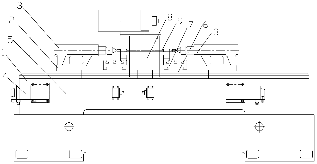
[0013] The machine tool for processing long bars of the present invention includes a bed 1, a clamping device, a driving device, and a guiding device.

[0014] The guiding device is mainly a guide rail 2 fixedly connected to the bed 1 so as to be used for sliding connection of the tailstock 3 in the clamping device. The driving device includes a large pallet 6 connected to the ball screw 5 of the z-axis servo motor 4, and a small pallet 7 that can be slidably connected to the large pallet 6 on the bed 1 to clamp the tool on the small pallet 7, so as to control the movement of the large pallet 6 and the small pallet 7, and realize the coordinate transformation between the tool and the workpiece 9 to be processed. The clamping device is fixedly arranged on the bed 1, and mainly includes a chuck box 8 fixedly connected to the bed 1 and a tailstock 9 that can be relatively slidably connected to the guide rail 2. In order to facilitate efficient processing of long bar workpieces, The...


PUM


Abstract

The invention discloses a machine tool for machining long bars. The machine tool comprises a machine tool body, a clamping device, a drive device and a guide device. The clamping device, the drive device and the guide device are disposed on the machine tool body. The guide device mainly comprises a guide rail fixedly connected to the machine tool body. The clamping device comprises a clamping plate box fixedly connected to the machine tool body and a tailstock slidably connected to the guide rail. The drive device comprises a large support plate and a small support plate which is relatively slidably connected to the large support plate. The machine tool is characterized in that another tailstock, another drive device and another guide device symmetrical to the clamping plate box are disposed on the machine tool body. A to-be-machined workpiece penetrates the chuck plate, one end of the to-be-machined workpiece is abutted against one tailstock, and the other end of the to-be-machined workpiece is abutted against the other tailstock. Due to the fact that the two ends of the to-be-machined workpiece are butted against corresponding tailstocks respectively, turning, threading and the like can be conveniently performed on the two ends, extending out of the clamping plate box, of the to-be-machined workpiece clamped to the clamping plate box.

Description

Technical field [0001] The invention relates to a machining machine tool, in particular to a long bar material machine tool with high machining efficiency and convenient machining. Background technique [0002] For long bar workpieces for turning and threading, for long bars that require turning and threading at both ends, the existing machine tool clamps the workpiece when the workpiece is clamped by the chuck box. One end and the other end are resisted by the tailstock which is slidingly connected to the guide rail to realize the processing of the non-clamped end of the workpiece. For the other end, the workpiece needs to be removed and turned, and the processed end is clamped in the chuck box. One end is pressed against the tailstock to complete the outer circle and threading of the unprocessed end. However, with this processing method, there are the following problems: 1. Both ends of the long bar material need to be clamped twice, which is inconvenient for processing. Time-...

Claims


Application Information

Patent Timeline
Patent Type & Authority Applications(China)
IPC IPC(8): B23B5/08B23B3/06
Inventor 柯金水
Owner ANHUI CHIZHOU HOUSEHOLD MACHINE TOOL
Why Eureka
Try Eureka