Hydraulic drive parallel moving robot

A mobile robot, parallel technology, applied in manipulators, program-controlled manipulators, manufacturing tools, etc., can solve the problems of limited driving force, unfavorable heavy-load shock, etc., and achieve the effect of increased working space, simple control, and large output power

Active Publication Date: 2013-12-25
BEIJING JIAOTONG UNIV
View PDF10 Cites 4 Cited by
  • Summary
  • Abstract
  • Description
  • Claims
  • Application Information

AI Technical Summary

Problems solved by technology

Due to the limited driving force of the mechanism motor, it is not conducive to heavy loads and large impacts. At the same time, the two ends of the branc

Method used


Image

  • Hydraulic drive parallel moving robot
  • Hydraulic drive parallel moving robot
  • Hydraulic drive parallel moving robot

Examples


Embodiment Construction

[0032] Below in conjunction with accompanying drawing, the present invention is described in further detail:

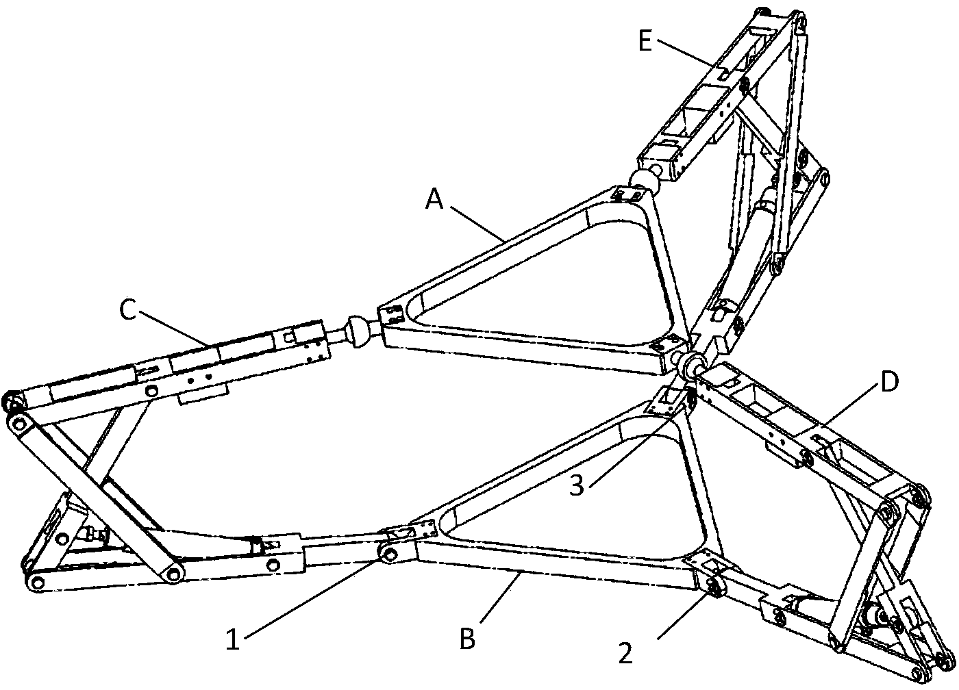
[0033] A hydraulically driven parallel mobile robot, such as figure 1 As shown, the hydraulically driven parallel mobile robot includes a spherical hinged triangular platform (A), a swivel hinged triangular platform (B), a first driving arm (C), a second driving arm (D), a third driving arm (E), and a third driving arm (E). A major axis (1), a second major axis (2) and a third major axis (3).

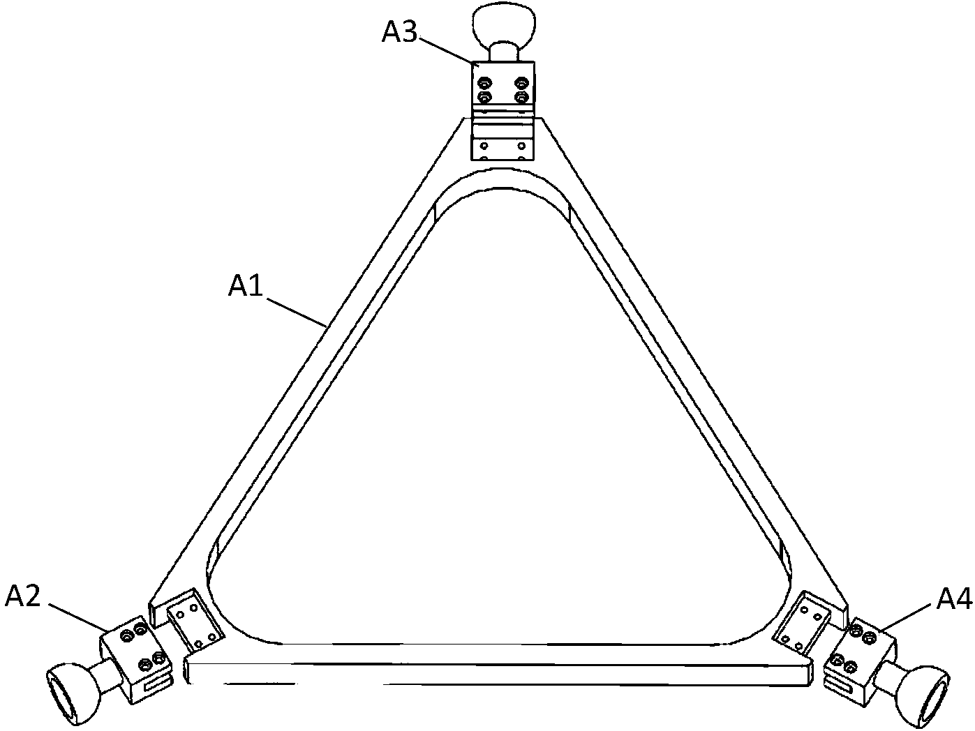
[0034] Such as figure 2 As shown, the ball hinge triangular platform (A) includes a first tripod (A1), a first ball groove (A2), a second ball groove (A3) and a third ball groove (A4).

[0035] The three top ends of the first tripod (A1) are provided with tongue-shaped bosses and through holes are opened on the bosses, the first ball groove (A2), the second ball groove (A3) and the first ball groove The three-ball groove (A4) has exactly the same structure and size, includi...


PUM


Abstract

The invention relates to a hydraulic drive parallel moving robot which comprises a spherical hinge triangular platform (A), a rotating hinge triangular platform (B), a driving arm (C), a driving arm (D), a driving arm (E), a long shaft (1), a long shaft (2) and a long shaft (3), wherein the three driving arms are respectively connected with the spherical hinge triangular platform and the rotating hinge triangular platform through a spherical pair and a rotating pair; each driving arm is a contra-parallelogram mechanism driven by a hydraulic cylinder; the robot deforms and moves by adjusting the telescopic change of the hydraulic cylinders which move independent of one another on the driving arms; by adopting the contra-parallelogram mechanisms as amplifying mechanisms, the work space and the deformation of the whole mechanism are greatly increased. By using the advantages of a hydraulic system, the hydraulic drive parallel moving robot has heavy load capacity; due to the adoption of a three-branched-chain parallel mechanism which has a degree of freedom being 3, the hydraulic drive parallel moving robot has the advantages of good stability, high rigidity, strong bearing capacity, stronger flexibility and deformation capability and capability of adapting to various complex environments.

Description

technical field [0001] The invention relates to the field of special robots, in particular to a hydraulically driven parallel mobile robot. technical background [0002] Chinese patent application CN3112512A discloses a rolling deformation mechanism. The mechanism is a parallel mechanism with three branch chains. Each branch chain is equipped with a drive motor, and the drive motor is installed in the middle of the branch chain to ensure the symmetry of the mechanism. The rolling deformation mechanism has strong flexibility and Deformation ability, by controlling the orderly forward and reverse rotation of the three motors, the forward movement of the rolling deformation mechanism and the steering movement can be realized. Due to the limited driving force of the mechanism motor, it is not conducive to heavy loads and large impacts. At the same time, the two ends of the branch chain are two hemispherical blocks, and the mechanism cannot separate the static platform and the d...

Claims


Application Information

Patent Timeline
IPC IPC(8): B25J9/00B25J9/14
Inventor 姚燕安沈海阔丁万黄齐来
Owner BEIJING JIAOTONG UNIV
Why Eureka
Try Eureka