Ink box chip, ink box and ink box adaptive support

An ink cartridge adapter frame and ink cartridge chip technology, which is applied in printing and other directions, can solve the problems that the ink cartridge cannot be detected, turned on and turned off at the same time, etc.

Active Publication Date: 2013-12-25
APEX MICROELECTRONICS CO LTD
View PDF6 Cites 10 Cited by
  • Summary
  • Abstract
  • Description
  • Claims
  • Application Information

AI Technical Summary

Problems solved by technology

[0006] However, the characteristic of the existing ink cartridge chips is that when several ink cartridge chips are installed in the same imaging device, the light sources controlled by them will emit light at the same time. cartridges, you will see that the light sources on all cartridges are on and off at the same time at any time
Since the ink cartridge position detection technology detects th

Method used


Image

  • Ink box chip, ink box and ink box adaptive support
  • Ink box chip, ink box and ink box adaptive support
  • Ink box chip, ink box and ink box adaptive support

Examples


Embodiment 1

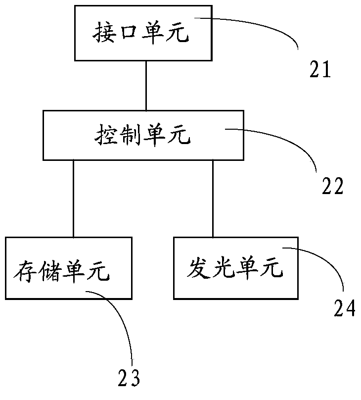
[0062] refer to figure 2 , figure 2 The structural diagram of the ink cartridge chip provided for this embodiment, wherein the ink cartridge chip includes: an interface unit 21, a control unit 22 and a storage unit 23, and the control unit 22 is connected to the light emitting unit 24;

[0063] The interface unit 21 is configured to receive a light control command sent by the imaging device, where the light control command includes ink cartridge identification information;

[0064] In this embodiment, the light control instruction includes ink cartridge identification information, and the ink cartridge identification information is used to identify the ink cartridge, and can be used to distinguish ink cartridges with different colors of ink. At the same time, the light control instruction also includes instruction information for instructing to turn on or turn off the light emitting unit. The light control instruction includes two types of instructions, namely, a light-on in...

Embodiment 2

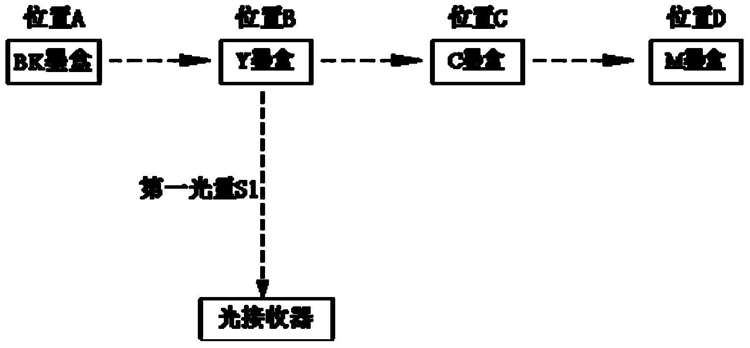
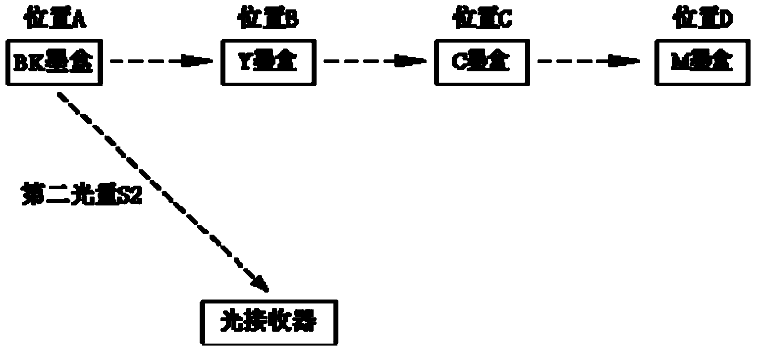
[0110] Some existing imaging devices also need to perform revolving door detection before performing light detection on the ink cartridge. by Figure 4 Take the arrangement of ink cartridges as an example. The so-called carousel detection means to let the light receiver face one of the ink cartridges, and then light up the light-emitting units of the ink cartridges from one direction to the other in sequence, for example, start from the left and light up sequentially. The light-emitting units on the ink cartridges C, M, Y and BK each once to judge whether the light receiver has been receiving light. The ink cartridge chip in the above embodiments may not meet the revolving door inspection requirements of the imaging device, causing the imaging device to consider the ink cartridge to be unqualified or illegal. Therefore, the ink cartridge chip provided by this embodiment can not only satisfy the light detection of the imaging device, but also satisfy the carousel detection of ...

Embodiment 3

[0145] The ink cartridge chip provided in this embodiment has a structure similar to that of Embodiment 1, and also includes an interface unit, a control unit, a storage unit and a light emitting unit. The connection relationship and existence form of each unit of the ink cartridge chip of this embodiment are the same as those of the ink cartridge chip of Embodiment 1, and will not be repeated here, only the differences are introduced. the

[0146] The storage unit of the ink cartridge chip provided in this embodiment at least stores self-identification information. It is worth noting that the control unit of the ink cartridge chip provided in this embodiment can only execute the light extinguishing instruction, and turn off the light emitting unit when the preset extinguishing condition is satisfied. the

[0147] Specifically, when the ink cartridge chip is powered on, the control unit detects that the ink cartridge chip is in the power-on initialization stage, and then lig...


PUM


Abstract

An embodiment of the invention discloses an ink box chip which comprises an interface unit, a control unit and a storage unit. The interface unit is used for receiving light control commands sent by an imaging device, the light control commands comprise ink box identification information, the storage unit is used for storing self identification information and state signs, the state signs comprise executable states or non-executable states, the control unit is connected with any one of light-emitting units and used for executing the light control commands, and the light control commands comprise light lightening commands or light extinguishing commands. The control unit is used for controlling the light-emitting unit to execute the light control commands according to the light control commands and the state signs in the storage unit when the interface unit receives the light control commands, and determining state signs again according to the incidence relation of the ink box identification information and the self identification information after the light-emitting unit executes the light control commands. The ink box chip can achieve detection of the position of the ink box in the imaging device.

Description

technical field [0001] The invention relates to the field of printing and imaging, in particular to an ink cartridge chip, an ink cartridge and an ink cartridge adapter frame. Background technique [0002] The present invention claims the priority of the Chinese application whose application number is 201210519186.2 whose filing date is November 22, 2012 and the Chinese application whose application number is 201310303587.9 whose filing date is July 11, 2013. the [0003] Imaging equipment is a common tool in people's work and life at present, such as printers, photocopiers and fax machines. The structure of the imaging device is roughly divided into two parts, namely, the main body of the imaging device and the ink cartridge. Ink cartridges are consumable items, so they are usually detachably installed in the main body of the imaging device and are easily replaced. the [0004] Existing imaging devices may be provided with multiple ink cartridges, which is beneficial fo...

Claims


Application Information

Patent Timeline
IPC IPC(8): B41J2/175
Inventor 周维李钜辉陈浩罗艳辉
Owner APEX MICROELECTRONICS CO LTD
Why Eureka
Try Eureka