
Bridge expansion joint trussed beam box

A technology of expansion joints and truss beams, which is applied to bridges, bridge parts, bridge construction, etc., can solve the problems of high steel bar density, emptying of the support box of the expansion device, and low concrete slump, so as to reduce the cost of the service life and durability Improve stability and avoid the effect of empty force

Inactive Publication Date: 2013-12-25
湖南广和桥梁构件有限公司
View PDF6 Cites 2 Cited by
  • Summary
  • Abstract
  • Description
  • Claims
  • Application Information

AI Technical Summary

Problems solved by technology

One kind of installation defect is the defect of the reserved installation notch of the bridge: the gap at the beam end of the notch is too wide, which may easily cause the bottom of the support box to be empty due to the suspended installation of the telescopic device, and the defect of not enough depth of the notch may easily cause the bottom of the truss girder box due to the narrow space , concrete is difficult to pour dense
Another installation defect is the concrete pouring defect of the telescopic device: due to reasons such as poor formwork production, insufficient concrete vibration, insufficient concrete strength, low concrete slump, and high steel bar density, the bottom of the truss box is empty or the concrete The direct cause of poor pouring
During the assembly process, transportation engineering, and installation process of the telescopic device, the truss girder may move left and right within the truss girder to a large extent, which may easily cause the truss girder to not align with the forward force support, resulting in partial load of the support Forced, accelerated damage to the force-transmitting support

Method used


Image

  • Bridge expansion joint trussed beam box
  • Bridge expansion joint trussed beam box
  • Bridge expansion joint trussed beam box

Examples


Embodiment Construction

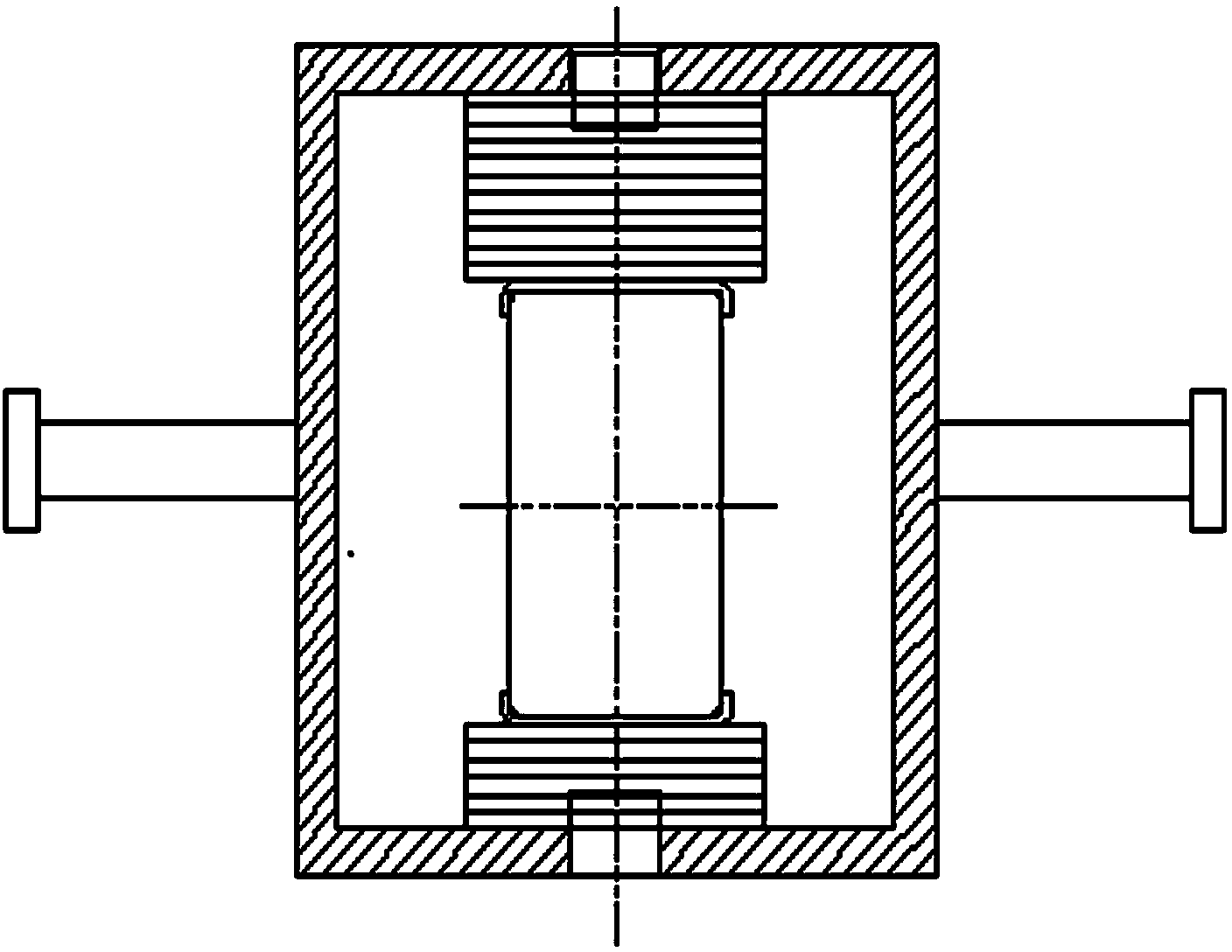
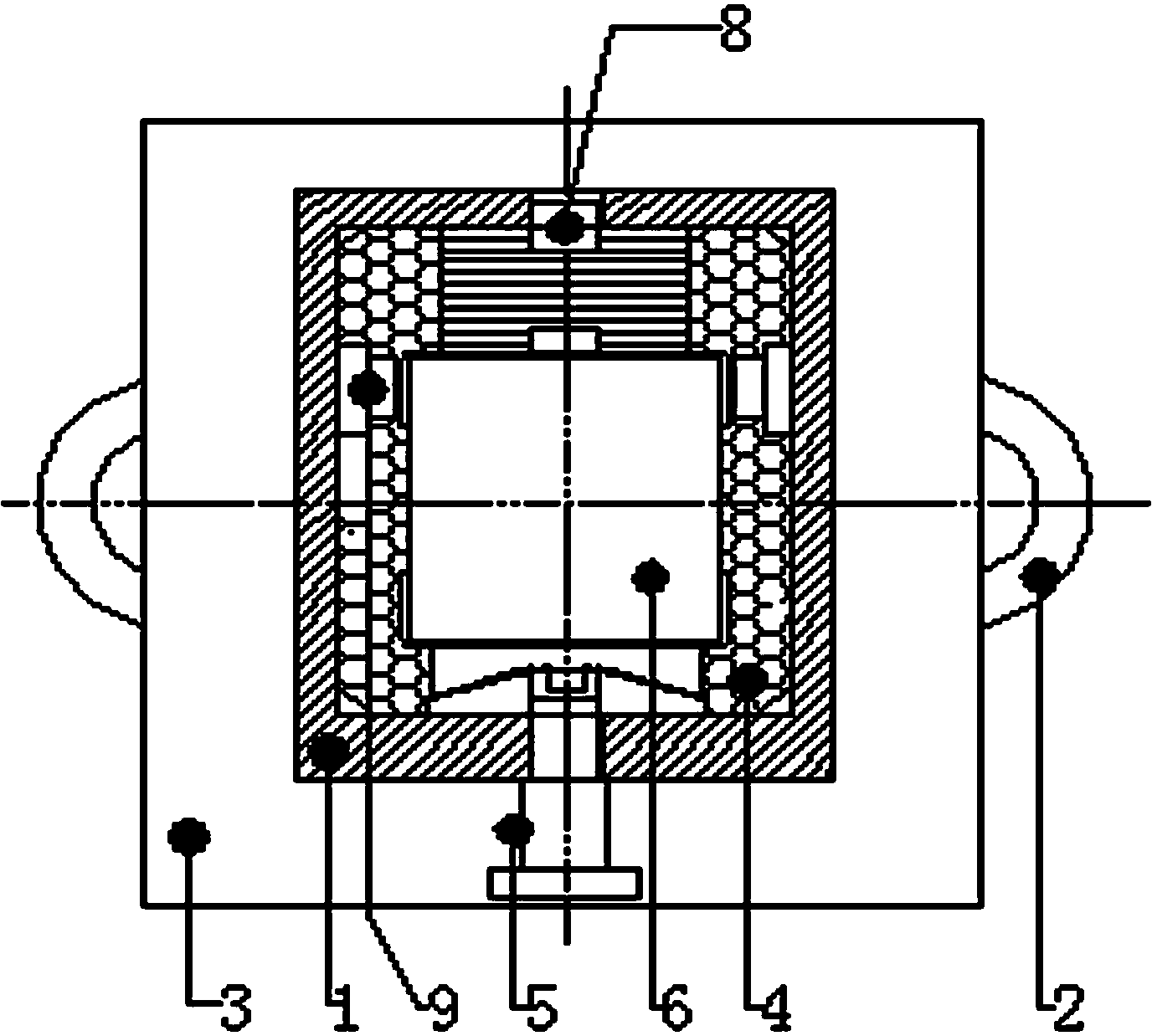
[0020] Such as Figure 1 to Figure 3 As shown, the bridge expansion joint truss box disclosed by the present invention comprises a cuboid truss box 1 located on both sides of the side beam 7, the longitudinal side wall of the truss box 1 has an annular anchor bar 2, and the inner end surface has a Reinforced coaming 3, the surroundings of the reinforced coaming 3 all protrude from the outer edge of the end face, and holes of corresponding shapes are arranged at the inner cavity corresponding to the inner end face, for the girder 6 to pass through. There are multiple groups of annular anchor bars 2 on the longitudinal side walls of the supporting box 1, and the two ends of the annular anchor bars 2 are welded and fixed to the side walls of the truss box 1 to prevent the overall settlement of the truss box 1. The reinforced coaming 3 and the truss box body 1 are connected by welding, which can be cut from one whole steel plate or tailor-welded from several steel plates. The rei...


PUM


Abstract

The invention discloses a bridge expansion joint trussed beam box which comprises a cuboid-shaped trussed beam box body. A longitudinal side wall of the trussed beam box body is welded with an annular anchor bar preventing sedimentation, the inner end face is welded with a reinforcing coaming which can prevent the side wall from being cracked in tension, the bottom face of the reinforcing coaming can resist bending and vibration, the periphery of the reinforcing coaming stretches out of the outer edge of the end face, and an inner cavity in the inner end face of the corresponding trussed beam box body is provided with a hole in the corresponding shape. A big-head supporting nail is arranged at the bottom. Compared with the prior art, according to the structure, the bridge expansion joint trussed beam box can not be dependent on concrete bearing on the bottom, use is safe, and even if the size of a reserved installation groove opening in a bridge has the large error, or in the process of installation, defects exist in the concrete construction, normal use of an expansion device can not be affected. On the other hand, according to the structure, main factors which affect the service life of the expansion device can be solved properly in the factory so as to come true, and the durable stability of the expansion device can be greatly improved.

Description

technical field [0001] The invention relates to a bridge expansion joint truss girder box, in particular to a bridge expansion joint truss girder box which does not rely on bottom concrete for bearing. Background technique [0002] At present, the structural design of the existing large-displacement modulus bridge expansion device does not fully consider the influence of various environmental factors during the installation of the product, and relies too much on the installation quality to ensure the service life of the product (see attached Figure 4 ). There are two installation defect factors that have the greatest impact on the service life of the telescopic device. One kind of installation defect is the defect of the reserved installation notch of the bridge: the gap at the beam end of the notch is too wide, which may easily cause the bottom of the support box to be empty due to the suspended installation of the telescopic device, and the defect of not enough depth of t...

Claims


Application Information

Patent Timeline
Patent Type & Authority Applications(China)
IPC IPC(8): E01D19/06
Inventor 李忠贵
Owner 湖南广和桥梁构件有限公司
Learn More