Sucking disc cover with convex ribs and sucking disc
What is AI technical title?
AI technical title is built by Patsnap AI team. It summarizes the technical point description of the patent document.
The technology of a suction cup cover and ribs is applied to a suction cup. It can solve the problems of low load-bearing capacity and durable performance of the suction cup, insufficient pressure contact area, and insufficient suction of the suction cup, and achieve the effects of simple structure, convenient production and high production efficiency.
Inactive Publication Date: 2013-12-25
ZHONGSHAN TAILI HOUSEHOLD PROD MFG
View PDF8 Cites 3 Cited by
Summary
Abstract
Description
Claims
Application Information
AI Technical Summary
This helps you quickly interpret patents by identifying the three key elements:
Problems solved by technology
Method used
Benefits of technology
Problems solved by technology
[0002] Suction cups are widely used because they are easy to use. They only need to be pressed on the base surface such as the wall and do not need to drill the wall. fall off, so it is necessary to improve the structure of the existing suction cup
Although the traditional suction cup can be adsorbed on the base surface such as the wall, the pressure contact area between the suction cup cover on the suction cup and the elastic colloid is not large enough, so the contact friction between the suction cup and the base surface such as the wall is biased. Small, resulting in low load-bearing capacity and long-lasting performance of the suction cup
Method used
Image
Click on the blue label to locate the original text in one second.
Reading with bidirectional positioning of images and text.
Examples
Embodiment 1
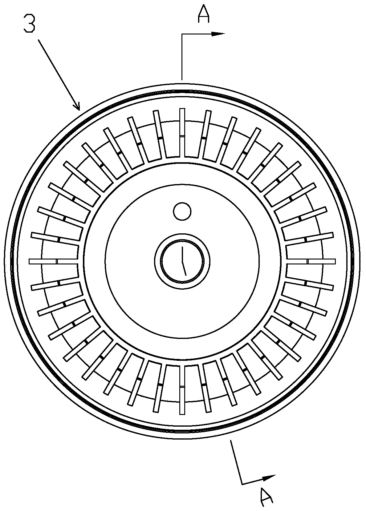
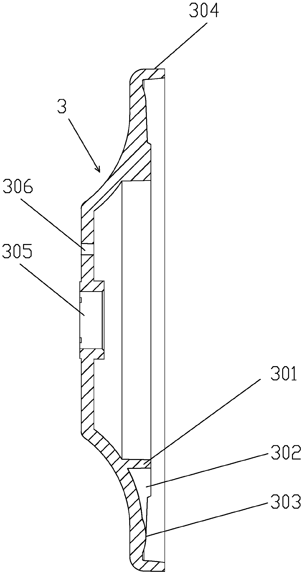
[0030] Such as Figure 1 to Figure 2 As shown, a suction cup cover with ribs includes a housing 304 with an open end, a through hole 305 is provided in the middle of the bottom surface of the housing 304, and a connecting rod from the housing is provided on the periphery of the through hole 305. 304 is an inner convex ring 301 whose bottom surface extends toward the opening side, and a plurality of ribs 302 are arranged on the outer side of the inner convex ring 301 .
[0031] The ribs 302 are arranged radially on the outside of the inner convex ring 301
[0032] An outer convex ring 303 is disposed on the periphery of the inner convex ring 301 , and the convex ribs 302 are arrayed circumferentially between the inner convex ring 301 and the outer convex ring 303 .
[0033] A concave platform 3021 is provided on the raised rib 302 .
[0034] The suction cup cover 3 is provided with a positioning hole 306 . Positioning holes 306 are provided to cooperate with external positio...
Embodiment 2
[0041] Such as Figure 8 to Figure 9 Shown, the difference of embodiment 2 and embodiment 1 is:
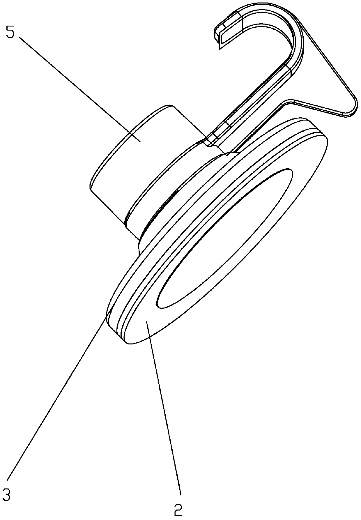
[0042] The pressing part 5 is a lever hinged with the upper end of the connecting rod 101, and the lever is provided with a protruding part 701 for pressing the back of the suction cup cover 3 when the suction cup is in use. .
[0043] The suction cup of the present invention can be used for hangers such as suction cup hooks and suction cup hanging baskets that need to be side hung on smooth, rough, dense and airtight walls.
[0044] The working principle of the present invention:
[0045] The working principle of embodiment 1:
[0046] Such as Figure 6 As shown, when in use, the suction cup is pressed on the base surface 10, the bottom surface of the elastic colloid 2 is attached to the base surface 10, and then the pressing member 5 is rotated, and the pressing member 5 presses the suction cup cover 3, and the suction cup cover 3 The radial ribs 302 of the elastic colloid ...
PUM
Abstract
The invention relates to a sucking disc cover with convex ribs. The sucking disc cover comprises a casing with one open end, wherein a through hole is formed in the middle of the bottom face of the casing, an inner convex ring extending towards one side of an opening from the bottom face of the casing is arranged on the periphery of the through hole, and multiple convex ribs are arranged on the outer side of the inner convex ring. The invention further relates to a sucking disc. The sucking disc comprises a framework, wherein an elastic rubber body is wrapped on the framework, the back portion of the framework is provided with a connecting rod, and the sucking disc cover is sleeved on the connecting rod. The inner convex ring and the convex ribs on the sucking disc cover abut against the back portion of the elastic rubber body, and the back side of the sucking disc cover is provided with an abutting-against part abutting against the back portion of the sucking disc cover and connected with the connecting rod. The sucking disc is provided with the sucking disc cover, the inner convex ring and the convex ribs of the sucking disc cover abut against the back portion of the elastic rubber body, the pressure-exerting contact area between the sucking disc cover and the elastic rubber body is increased, and accordingly the sucking disc has enough vacuum suction force and friction force between the sucking disc and a basal plane in use.
Description
【Technical field】 [0001] The invention relates to a suction cup cover with ribs, and also relates to a suction cup using the suction cup cover. 【Background technique】 [0002] Suction cups are widely used because they are easy to use. They only need to be pressed on the base surface such as the wall and do not need to drill the wall. come off, so it is necessary to improve the structure of the existing suction cup. Although the traditional suction cup can be adsorbed on the base surface such as the wall, the pressure contact area between the suction cup cover on the suction cup and the elastic colloid is not large enough, so the contact friction between the suction cup and the base surface such as the wall is biased. Small, resulting in low load-bearing capacity and durable performance of the suction cup. [0003] The present invention is made based on this situation. 【Content of invention】 [0004] The invention overcomes the deficiencies of the prior art, and provides...
Claims
Application Information
Patent Timeline
Application Date:The date an application was filed.
Publication Date:The date a patent or application was officially published.
First Publication Date:The earliest publication date of a patent with the same application number.
Issue Date:Publication date of the patent grant document.
PCT Entry Date:The Entry date of PCT National Phase.
Estimated Expiry Date:The statutory expiry date of a patent right according to the Patent Law, and it is the longest term of protection that the patent right can achieve without the termination of the patent right due to other reasons(Term extension factor has been taken into account ).
Invalid Date:Actual expiry date is based on effective date or publication date of legal transaction data of invalid patent.

